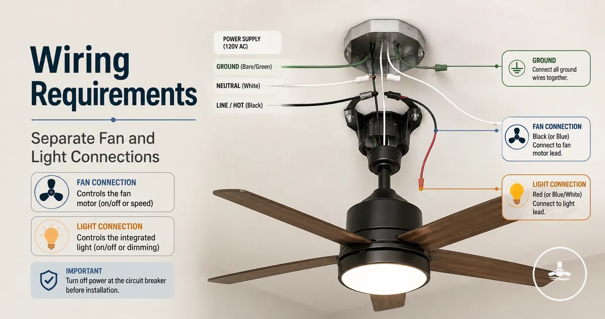
Ceiling fans with lights wiring requirements
For an Australian ceiling fan with light, wiring suitability depends on a verified supply, correctly identified conductors, a control method that matches the fan and light functions, and a structurally suitable ceiling mounting point. Do not identify a conductor by colour alone: newer Australian fixed wiring commonly uses brown active, blue neutral and green/yellow earth, older wiring may use different colours, and fan or receiver leads follow the manufacturer’s own diagram. Fixed-wiring connection or alteration should be assessed and performed by a licensed electrician.
Wiring readiness decision guide
Use these five checks to decide whether the existing point is ready for product-compatibility review or needs electrical assessment first. This is a decision aid, not a wiring diagram.
Circuit condition
Supply, cable condition and access are known and serviceable. Damage, heat marks, inaccessible joins or uncertainty mean assessment first.
Conductor identity
Active, neutral, protective earth and any control conductors are identified by testing or reliable documentation, not by colour alone.
Control layout
The installation is known to use combined wall control, separate control paths, a compatible receiver, or another manufacturer-supported controller.
Fan and receiver compatibility
The exact manufacturer diagram matches the available supply and control arrangement; internal lead colours are treated as product-specific.
Mounting and enclosure
The bracket, structure and connection enclosure are suitable for a ceiling fan. A former light-fitting point is not automatically adequate for fan movement and load.
Decision rule: if any conductor role, cable condition, control pathway or mounting condition is unknown, treat the installation as not yet verified and obtain licensed electrical assessment. If all are known, compare the existing arrangement with the exact fan or receiver instructions before selection or installation.
The control method determines whether the fan and light share one wall-controlled supply, use verified independent control paths, or are managed by a compatible receiver. The manufacturer diagram defines the product-side connections; the ceiling fans with lights guide provides broader context for comparing controls, installation needs and product fit.
Existing circuit and cable conditions before wiring a ceiling fan with light
Before a ceiling fan with light is matched to an existing point, the circuit condition, conductor availability, control arrangement, cable condition, ceiling access and mounting support should be known. The practical outcome is one of three states: suitable for compatibility review, requires licensed electrical verification, or requires remedial work before a fan is considered.
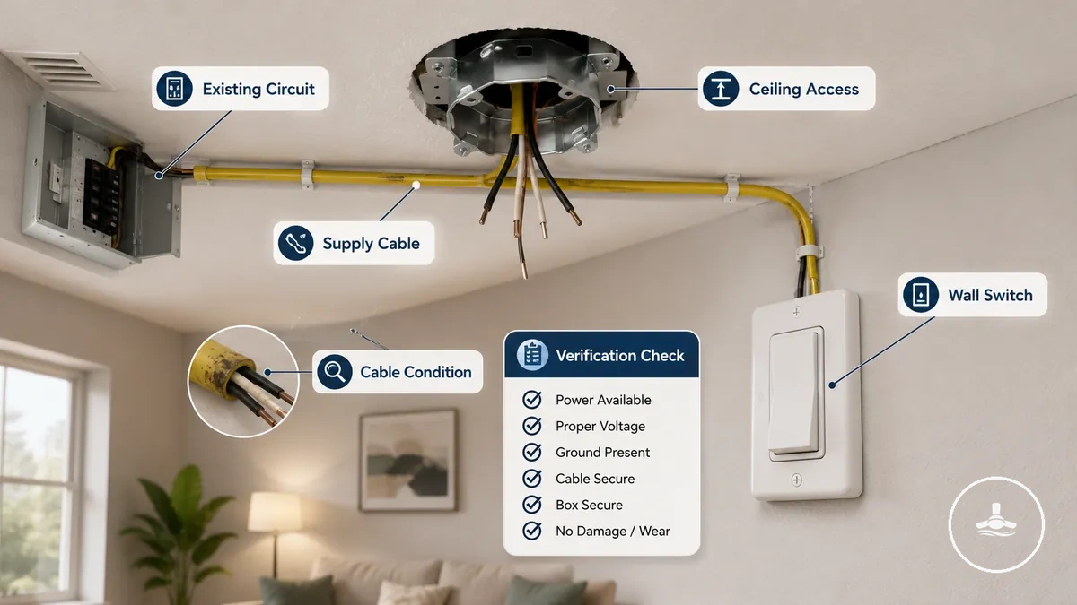
Existing-point readiness checklist
- Supply and cable condition: the circuit is serviceable, with no visible damage or unresolved heat, insulation or junction concerns.
- Conductor roles: active, neutral, protective earth and any control conductors are positively identified rather than inferred from colour.
- Control pathway: the existing wall control or receiver arrangement is known, including whether independent fan/light control is actually supported.
- Ceiling access: the connection point can be inspected sufficiently to verify the existing arrangement; hidden or inaccessible joins increase uncertainty.
- Mounting support: the structure and bracket/fixing method are suitable for the fan model rather than assumed adequate because a light fitting was previously installed.
If any of these conditions is unknown, damaged or incompatible with the fan manufacturer’s requirements, the installation needs electrician assessment before a wiring layout is selected. The broader installation requirements page covers the structural and installation context beyond wiring alone.
Wire colours and conductor roles in ceiling fan light wiring
On an Australian page, fixed-wiring colours and fan/receiver lead colours must be kept separate. Newer fixed wiring commonly uses brown for active, blue for neutral, and green/yellow for protective earth; older Australian wiring may use legacy colours such as red active and black neutral. A fan, light kit or receiver can use different internal lead colours, so its manufacturer diagram—not the building-wire colour pattern—defines those product-side roles.
Colour therefore provides context, not proof. Conductor function should be verified at the installation point, especially in older homes, altered circuits, imported equipment or receiver-based systems where internal harness colours may resemble fixed-wiring colours but mean something different.
The illustration below is a conceptual wiring aid only. It should not be read as an Australian fixed-wiring colour standard or as connection instructions.
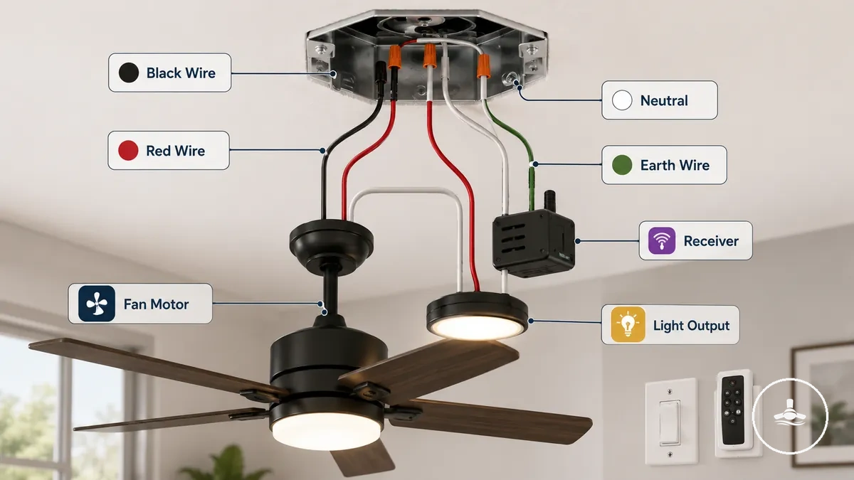
The table separates where a colour appears from the role it commonly signals, which prevents legacy fixed wiring from being confused with manufacturer-specific appliance leads.
| Where the conductor is found | Common colour pattern | Typical role | Interpretation rule |
|---|---|---|---|
| Newer Australian fixed wiring | Brown | Active | Verify function before work; do not infer switching state from colour alone. |
| Newer Australian fixed wiring | Blue | Neutral | Do not confuse fixed-wiring blue neutral with a blue product lead that a manufacturer may assign to another function. |
| Australian fixed wiring | Green/yellow | Protective earth | Earthing requirements and continuity must match the equipment and installation. |
| Older Australian fixed wiring | Red | Common legacy active colour | Legacy installations can contain alterations or other colour schemes; positive identification is still required. |
| Older Australian fixed wiring | Black | Common legacy neutral colour | Black must not be assumed to be a fan-motor active simply because some product harnesses use black differently. |
| Fan, light kit or receiver leads | Black, white, blue, red or other colours | Manufacturer-specific input, output, motor, light or control function | Follow the exact fan or receiver wiring diagram; appliance-lead colours are not a substitute for fixed-wiring identification. |
The decisive value is the verified conductor role, not the visual colour. This is especially important when older fixed wiring and a modern fan receiver appear in the same ceiling space.
Black, red, white, and earth wires in fan and light connections
Black, red, white and earth-coloured conductors can appear in legacy wiring or inside fan and receiver harnesses, but they do not form one universal Australian ceiling-fan colour code. The same colour can carry a different meaning depending on whether it belongs to the building wiring or to the fan manufacturer’s internal leads.
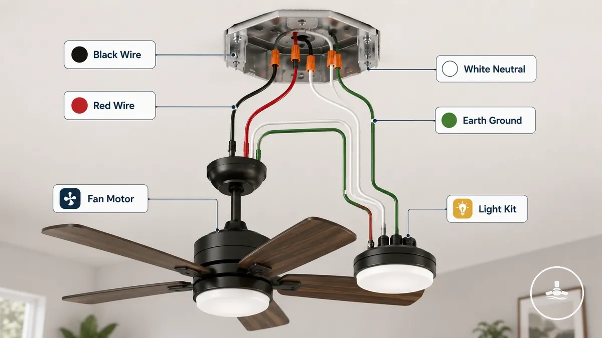
- Black — commonly appears as a legacy neutral in older Australian fixed wiring, but some product harnesses assign black to a motor or supply lead; context and verification are essential.
- Red — commonly appears as a legacy active in older Australian fixed wiring; a product or receiver can assign red differently, so the manufacturer diagram still controls the product-side meaning.
- White — is not the current standard neutral colour for Australian fixed wiring. It can appear in fan or receiver leads and must be interpreted from the product documentation.
- Protective earth — current fixed wiring is commonly green/yellow; legacy installations may differ. The relevant requirement is a verified protective-earth path where the equipment requires earthing.
The practical rule is simple: first identify whether the conductor belongs to fixed wiring or the fan/receiver assembly, then confirm its function from testing and the exact product documentation.
Unused or missing wires in common ceiling fan wiring setups
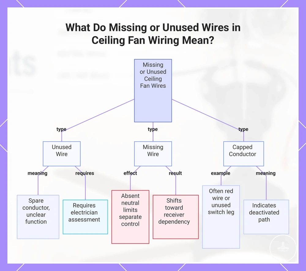
Unused, capped or apparently missing conductors do not by themselves reveal what control options are available. The effect depends on which conductor is absent, where it is absent, and what the selected fan or controller requires.
| Condition | What it can mean | Decision effect | Safe next step |
|---|---|---|---|
| Unused or capped conductor | Spare, abandoned or previously used control path | Does not prove that a usable fan/light control conductor is available | Have its function identified before relying on it. |
| Neutral absent at a wall switch location | Some switching arrangements do not bring neutral to the wall plate | Can prevent wall controls that specifically require a neutral at that location | Compare the controller requirements with the verified circuit arrangement. |
| Required neutral absent at the ceiling connection point | The available supply may not match many fan or receiver arrangements | A receiver does not automatically solve a missing required neutral | Licensed electrical assessment or circuit alteration may be required. |
| Extra conductors present | They may be control, switched, spare or repurposed conductors | Presence alone does not establish independent fan/light control | Verify each role and whether the fan design supports that control method. |
In practice, conductor availability can limit combined versus independent control, but receiver dependency should never be inferred from a missing conductor. The exact receiver and fan requirements must be matched to the verified circuit.
The image below summarises how missing or unused conductors change the assessment question rather than provide a wiring answer.
Control layouts that change how the fan and light are wired
The control layout determines which electrical and control pathways the fan needs. A combined wall switch, separate wall controls, a remote receiver and a mixed wall/receiver arrangement can all produce different compatibility requirements even when the same fan-and-light functions are desired.
| Control layout | What provides control | What must match | Main limitation |
|---|---|---|---|
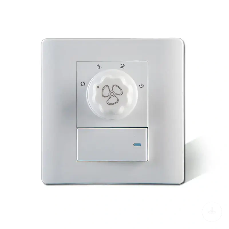
| Combined wall control | One wall-controlled supply to the fan assembly | The fan must support combined supply or use compatible onboard/receiver control for separate functions | A single wall control does not automatically provide independent fan and light switching. |
| Separate wall controls | Independent manufacturer-supported control paths or controller inputs | Fan design, wall controls and verified conductors/control interface | Extra wires or colours alone do not prove the arrangement is suitable. |
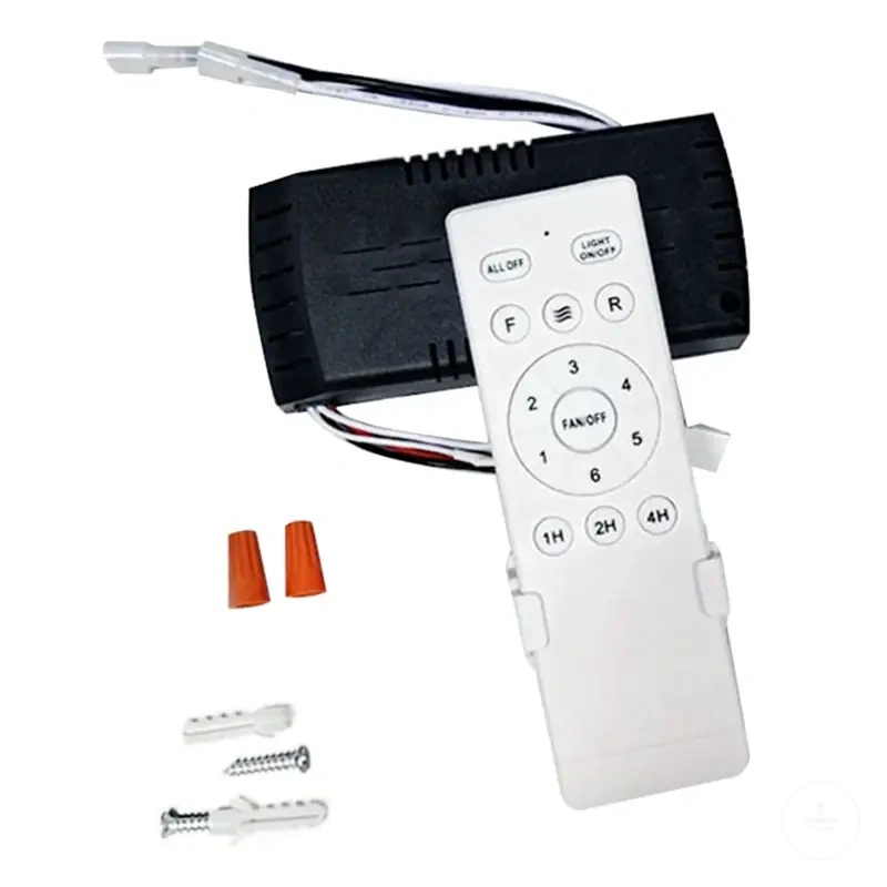
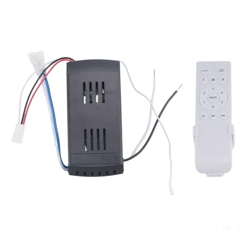
| Remote receiver | A compatible receiver manages fan motor and light outputs | Supply requirements, receiver model, motor type, connectors and fan instructions | Receiver terminal/output assignments are product-specific. |
| Mixed wall + receiver control | A manufacturer-supported combination of wall supply/isolation and receiver/controller logic | Both control devices must be explicitly compatible with the fan system | Overlapping or incompatible controllers can cause loss of control or unstable operation. |
The key distinction is between supplying power to the fan assembly and controlling the fan and light functions. A receiver or onboard controller can separate functions internally even when only one wall-controlled supply is present, while other fan designs require dedicated control arrangements.
When the existing control method does not match the fan design, choose a compatible control system or obtain professional assessment rather than repurposing an unidentified conductor. For related options, see wall controls and smart controls.
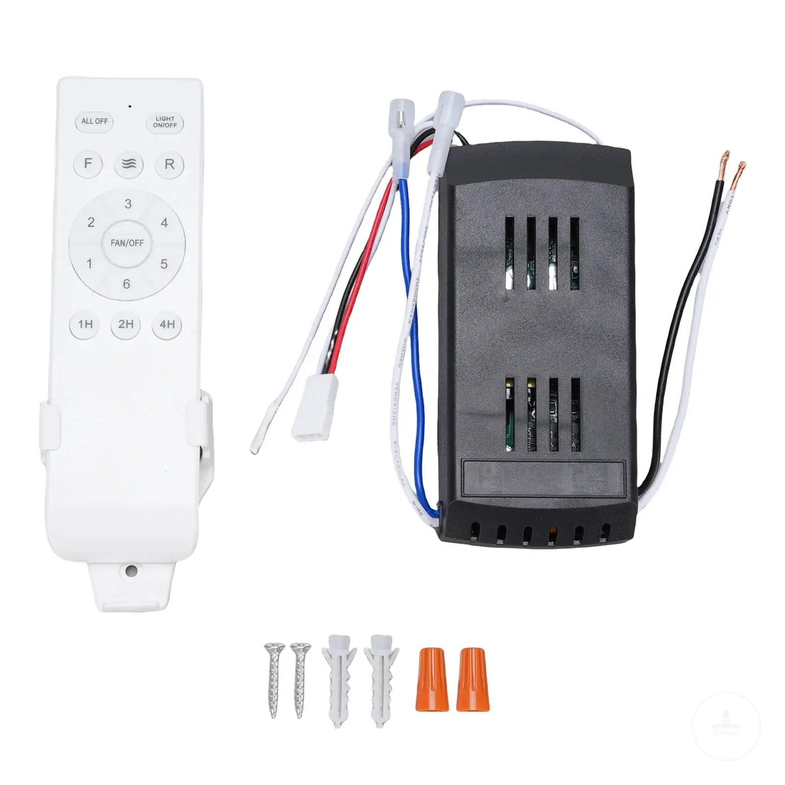
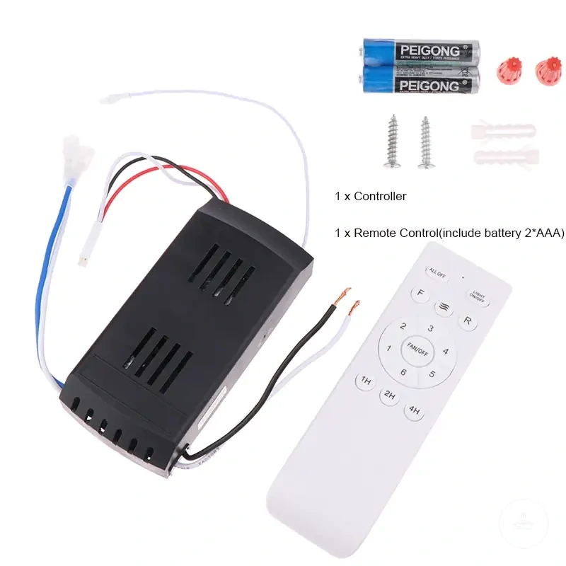
The existing product listings below illustrate receiver and wall-control categories discussed in this section. A product name such as “universal” does not prove compatibility: compare the fan motor type, supply requirements, receiver/control interface, connectors and manufacturer instructions before considering an affiliate referral.
One wall switch for combined fan and light control
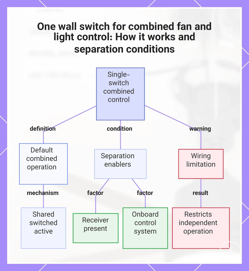
With one wall switch, the wall control commonly energises or isolates the fan assembly as a whole. Whether the fan motor and light then operate together or independently depends on the fan’s internal controls or a compatible receiver.
- No receiver or onboard separation: the available wall control may provide only combined on/off behaviour for the assembly, depending on the fan design.
- Compatible receiver present: the wall switch can supply the receiver while the receiver independently manages fan speed and light operation.
- Integrated electronic controls: some fans separate motor and light functions internally; the manufacturer specifies how wall power should be provided.
- Unknown or incompatible control: a single switch should not be treated as proof that every fan/receiver combination will work correctly.
The decision point is therefore the fan’s supported control architecture, not simply the number of wall switches.
The image below shows the control concept and the conditions under which one wall switch can still coexist with independent fan and light functions.
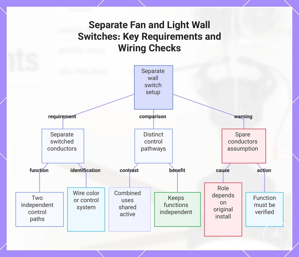
Separate wall switches for fan and light control
Separate wall controls can provide independent fan and light operation only when the fan system supports that method and the required verified control pathways or controller inputs are available. A red or blue conductor is not, by itself, evidence that one path is assigned to the fan and the other to the light.
What must be true
- The fan or controller is designed for separate external control.
- The required supply and control paths are positively identified.
- The wall controls are compatible with the fan motor, light and any receiver.
What is not proof
- A spare conductor is present.
- A conductor is red, blue, black or white.
- A two-gang wall plate previously controlled another fitting.
The image below summarises the comparison: independent control is a system compatibility condition, not a colour-matching exercise.
Remote receiver wiring between the supply, fan motor, and light
A remote receiver is an intermediate control module between the building supply and the fan assembly. It changes the control logic, but it does not remove the need for a suitable supply, correct conductor identification, protective earthing where required, or compliance with the fan and receiver instructions.
Verified supply
The existing circuit must meet the fan/receiver supply requirements.
Receiver input
The receiver accepts power and control only as specified by its manufacturer.
Receiver outputs
The module assigns motor and light functions through product-specific outputs or connectors.
Fan and light loads
Operation follows the compatible receiver/fan design rather than a universal terminal pattern.
Important: this sequence is a conceptual relationship, not a connection diagram. Terminal names, connectors, motor type and output allocation vary by manufacturer and model.
Remote and wall switch wiring in the same installation
A wall switch and remote receiver can coexist only when their responsibilities are compatible. The wall device may simply supply or isolate power, or it may be a dedicated controller designed to communicate with the fan system; these are different functions and should not be treated as interchangeable.
Compatibility checklist
- The fan manufacturer permits the proposed wall-control and receiver combination.
- The wall device’s role—power supply/isolation or active fan control—is clearly defined.
- The receiver is the correct type for the fan motor and light functions.
- Two incompatible controllers are not attempting to regulate the same motor or light input.
When these conditions are not met, control can become unreliable or unavailable. Treat the manufacturer-supported control combination as the compatibility value that matters, rather than assuming that any wall switch can be added to any receiver.
Connection points at the ceiling, canopy, receiver, and light kit
The wiring relationship is distributed across several physical locations: the ceiling connection/mounting point, canopy, optional receiver, fan body and light kit. These locations should be distinguished because structural support, fixed-wiring connections and product-side connectors are different functions even when they sit close together.
| Location | Primary role | What to identify | Common interpretation error |
|---|---|---|---|
| Ceiling connection / mounting point | Supply junction plus structural fixing area | Verified supply arrangement, enclosure where fitted, bracket and structural support | Assuming a former light-fitting point is automatically suitable for fan movement and load. |
| Canopy | Covers the mounting bracket and connection area | Available connection space, cable protection and component clearance | Treating the canopy itself as the structural support. |
| Receiver | Product-specific control module | Correct model, input/output labels, motor/light compatibility and connector arrangement | Assuming terminal names or lead colours are universal. |
| Fan body | Motor and internal control assembly | Manufacturer-designated motor/control connectors | Confusing internal product leads with building fixed wiring. |
| Light kit | Illumination assembly | Manufacturer-designated light/LED connector and supported control method | Assuming a light-kit lead maps directly to an existing ceiling conductor by colour. |
This distinction reduces two common errors: treating the mounting point as only an electrical junction, and treating internal fan/receiver conductors as though they follow the same colour conventions as Australian fixed wiring.
Ceiling mounting support, earthing, and wiring safety limits
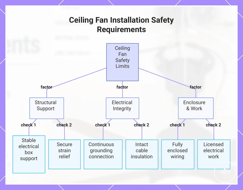
A safe ceiling-fan installation depends on both structural support and electrical integrity. The mounting bracket and structure must suit the fan, while conductors, earthing, enclosure, terminations and controls must be appropriate for the installed equipment and circuit.
Safety verification points
- Mounting support: the bracket and building structure are suitable for the fan model and its dynamic movement; an existing light-fitting support is not automatically adequate.
- Protective earthing: the earth path and the equipment’s earthing requirements are verified where earthing is required by the fan design.
- Connection enclosure: fixed-wiring connections remain protected inside a suitable enclosure, canopy or junction arrangement as applicable.
- Cable and termination condition: damaged insulation, heat damage, loose terminations or strained cables are stop-and-assess conditions rather than acceptable variations.
- Control compatibility: wall controls, dimmers, speed controllers and receivers are used only when the fan/light system is designed for them.
- Licensed electrical work: in Australia, fixed-wiring connection and alteration should be handled in accordance with applicable state or territory licensing requirements.
Structural and electrical checks are complementary: a sound circuit does not compensate for inadequate mounting, and a strong mounting point does not compensate for uncertain conductors or incompatible controls. The practical safety value is verified suitability in both domains.
For a broader pre-installation safety boundary, use the electrical safety checks page before treating the point as ready for installation.
The image below groups the main structural, earthing, enclosure and cable-condition checks that determine whether the installation should proceed to product-specific verification.
Wiring mistakes that can stop the fan light from working
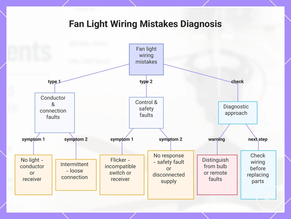
A ceiling fan light that does not work can be caused by wiring or control faults, but also by the lamp/LED module, remote settings, receiver failure or an incompatible control device. The first diagnostic distinction is therefore wiring-related versus component/control-related, not an assumption that a particular conductor is wrong.
| Symptom | Possible wiring/control cause | Other plausible cause | Safe next action |
|---|---|---|---|
| Fan works, light does not | Light-control path, receiver output or product-side connector problem | Failed lamp/LED module, remote setting or light-kit fault | Check normal user controls and replaceable lamp items first; if fixed wiring or receiver connections are uncertain, use licensed electrical service. |
| Fan and light both do not respond | Supply/control interruption or incompatible receiver/controller | Receiver, remote pairing, internal electronics or upstream circuit issue | Confirm the normal controls and documented product reset/pairing steps only; electrical supply faults require professional assessment. |
| Intermittent operation | Loose or stressed termination, intermittent controller/receiver path | Receiver electronics, connector or thermal protection issue | Stop using the unit if there is heat, smell, arcing or unusual noise; have the electrical and product connections assessed. |
| Light flickers | Incompatible control/dimmer, unstable receiver output or loose connection | LED driver, lamp or light-kit fault | Confirm the control is manufacturer-compatible; persistent flicker or any sign of connection damage warrants electrical assessment. |
Receiver output problems and incompatible switch or dimmer types can mimic wiring faults, so the diagnostic value comes from comparing the symptom, control state and product compatibility before replacing parts.
For symptom-specific guidance, see ceiling fan light not working and flickering ceiling fan light. These pages help separate user-serviceable checks from conditions that need electrical diagnosis.
The image below maps common fan-light symptoms to possible wiring and control causes while preserving the key limitation that a symptom alone does not prove a specific fault.