
Ceiling Fan Light Not Working: Causes, System Behavior, and Troubleshooting Scope
If the fan runs but its light does not, power is reaching at least part of the fan, so start with the lighting branch: the bulb or LED module, light control/receiver, and lighting connections. If both fan and light are unresponsive, start with the common power supply and controls; if there is sparking, scorching, a burning odour, overheating, exposed wiring, or a repeatedly tripping breaker, stop using the fixture and arrange qualified electrical assessment.

Find the fault area from the symptom
Choose the behaviour that best matches the fan. The result narrows the part of the system to check first; it does not confirm that a particular component has failed.
Most likely fault area: Lighting branch
Next safe check: If the fan uses a user-replaceable bulb, isolate power and try a known-good compatible bulb. If it uses an integrated LED or the bulb check does not solve the problem, compare the available controls before moving to model-specific service.
Use the result to prioritise checks, not as proof of a failed part. Do not open fixed wiring or perform live electrical tests unless you are qualified and permitted to do so.
A ceiling fan with a light is one electrical system with shared and separate branches. A running fan motor confirms that part of the fixture is energised, but it does not prove that power is reaching the light module; the lighting circuit can still fail independently.
Safe troubleshooting therefore moves from observable behaviour to the least invasive checks, then to model-specific service only when necessary. The sections below trace the power, control, light-source, wiring, and internal-component paths used by ceiling fans with lights.
Understanding Why a Ceiling Fan Light Stops Working and How the Lighting System Is Structured
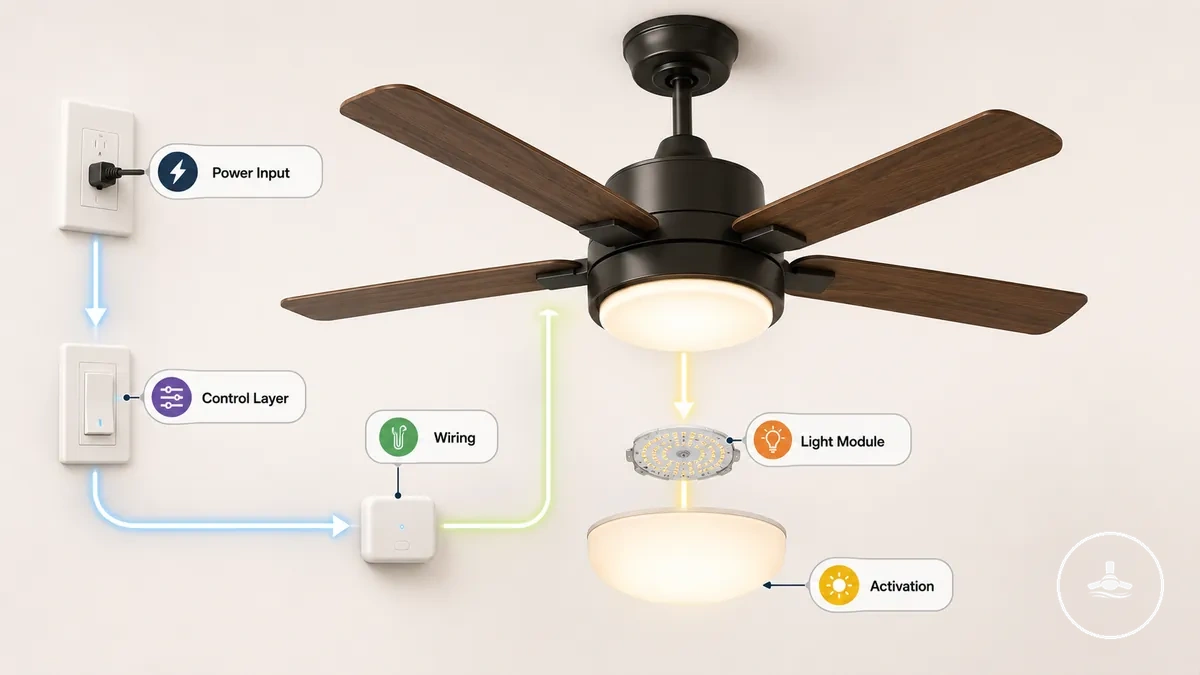
A ceiling fan light works as a chain: the circuit supplies power, a wall control, pull chain, receiver, or smart controller determines whether the lighting branch is activated, wiring and connectors carry that power, and the bulb or LED system produces light. The exact order and components vary by model.
Key diagnostic boundary
A running fan narrows the fault but does not prove the light circuit has power. The motor and lighting functions may share the incoming supply while using separate switched, receiver, wiring, driver, or light-source paths.
For troubleshooting, treat the system as supply → control → lighting connections → light source/driver. A break anywhere in that path can create the same visible result—no light—so the symptom should identify the next branch to check rather than a guessed replacement part.
Common Symptoms When a Ceiling Fan Light Stops Working or Becomes Unresponsive
The most useful first distinction is whether the fan motor still operates and whether the light fails consistently or intermittently. That observation changes which fault areas deserve attention first. If the light flashes instead of remaining steady, see flickering ceiling fan light for a focused explanation.
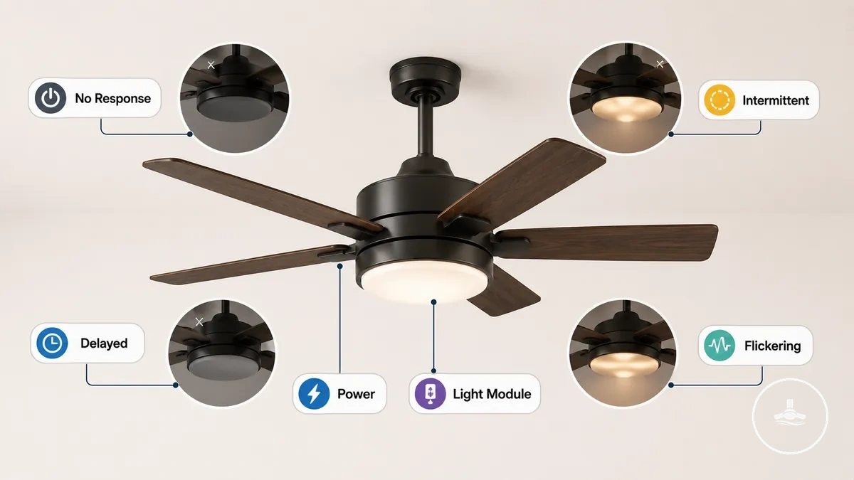
| Observed symptom | What it narrows | First interpretation or check |
|---|---|---|
| Fan runs; light stays off | Lighting branch rather than the entire fan supply | Check a user-replaceable bulb first when fitted, then compare controls; integrated LED designs may require driver, module, receiver, or light-kit service. |
| Fan and light are both unresponsive | Common supply or shared control path | Check the circuit breaker and wall control status before assuming a light-specific failure. |
| Intermittent light | Light-source contact, connection, control/receiver, or LED driver | Stop immediately if there is heat, sparking, scorching, or a burning odour; otherwise avoid live inspection and proceed from user-accessible checks. |
| Delayed activation | Control/receiver or LED-driver behaviour may be involved | Compare available control methods. A delay that occurs from every control path is more consistent with an internal lighting/control issue than a single handset problem. |
| One control works; another does not | The failed control path is more suspect than the light source | For a remote, check its battery and model-specific pairing. For a wall control that is hot, loose, damaged, or noisy, stop using it and seek electrical assessment. |
These patterns are diagnostic signals, not guaranteed diagnoses. Use them to choose the next safe check and confirm the cause with model-specific information before replacing internal parts.
Power Supply, Wall Switch, and Remote Receiver Issues Affecting Ceiling Fan Light Operation
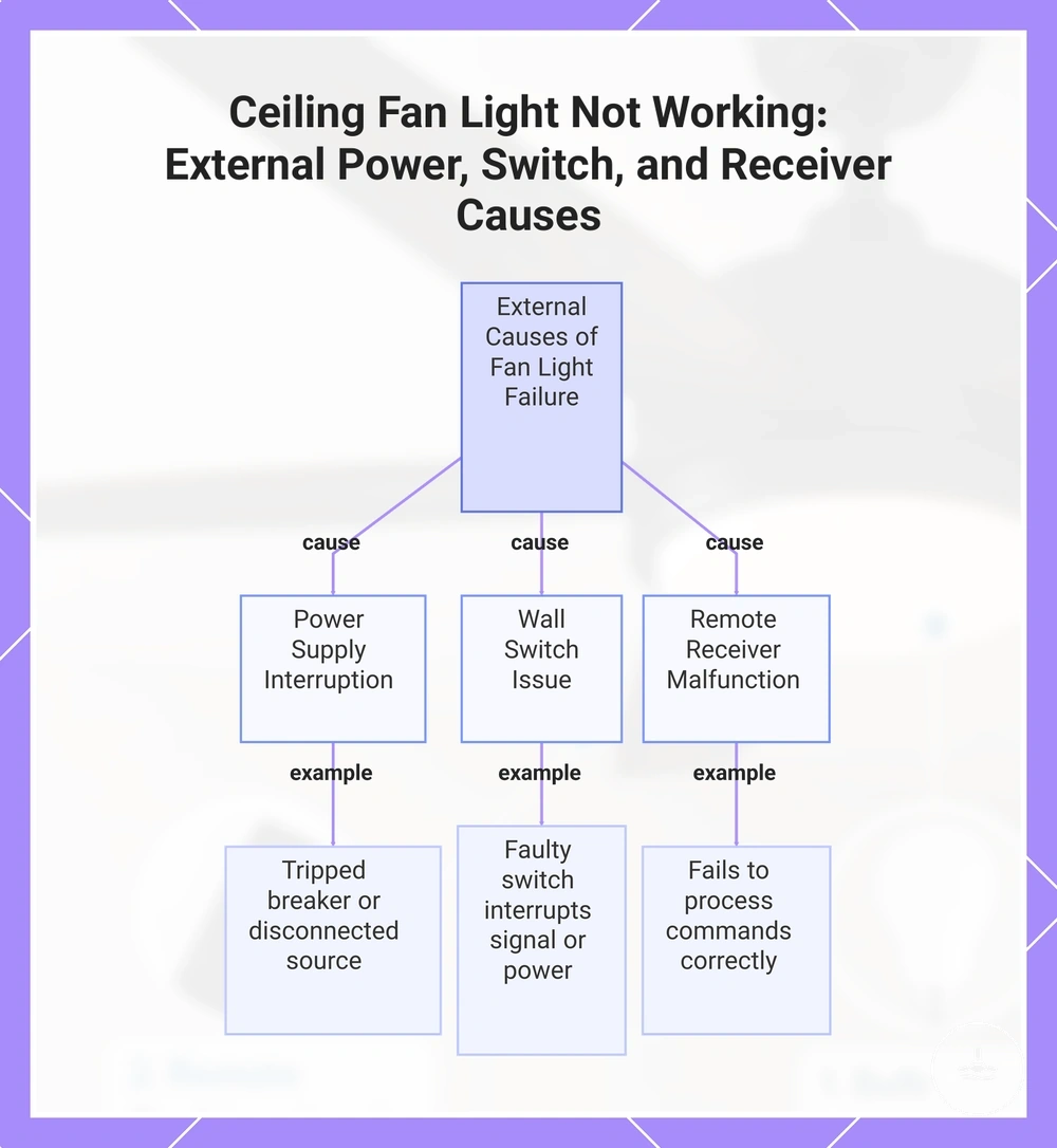
When the light does not respond, determine whether the interruption affects the whole fixture or only one control path. The circuit supply, wall control, and remote system perform different roles, so their failure patterns are not interchangeable.
| Part | Normal role | Fault pattern | Safe first check |
|---|---|---|---|
| Circuit supply / breaker | Provides the common electrical feed | Both fan and light may be unresponsive when the shared supply is interrupted | Check whether the breaker has tripped. Do not repeatedly reset a breaker that trips again. |
| Wall switch or wall control | Switches mains power or sends a control command, depending on the design | One or both functions may fail depending on the wiring and controller | Confirm the normal operating position. A hot, loose, damaged, or crackling control should not be used. |
| Remote handset / receiver | The handset sends a command; the receiver interprets it and switches or regulates the fan functions | The fan may respond while the light does not, or neither function may respond through the remote path | Check the handset battery and pairing instructions first. Internal receiver access is a service task when it involves fixed wiring. |
The existing chart visually summarises these external power and control fault areas; the table adds the role and first safe distinction for each one.
Bulb, LED Module, and Light Kit Failures Causing Complete Light Loss
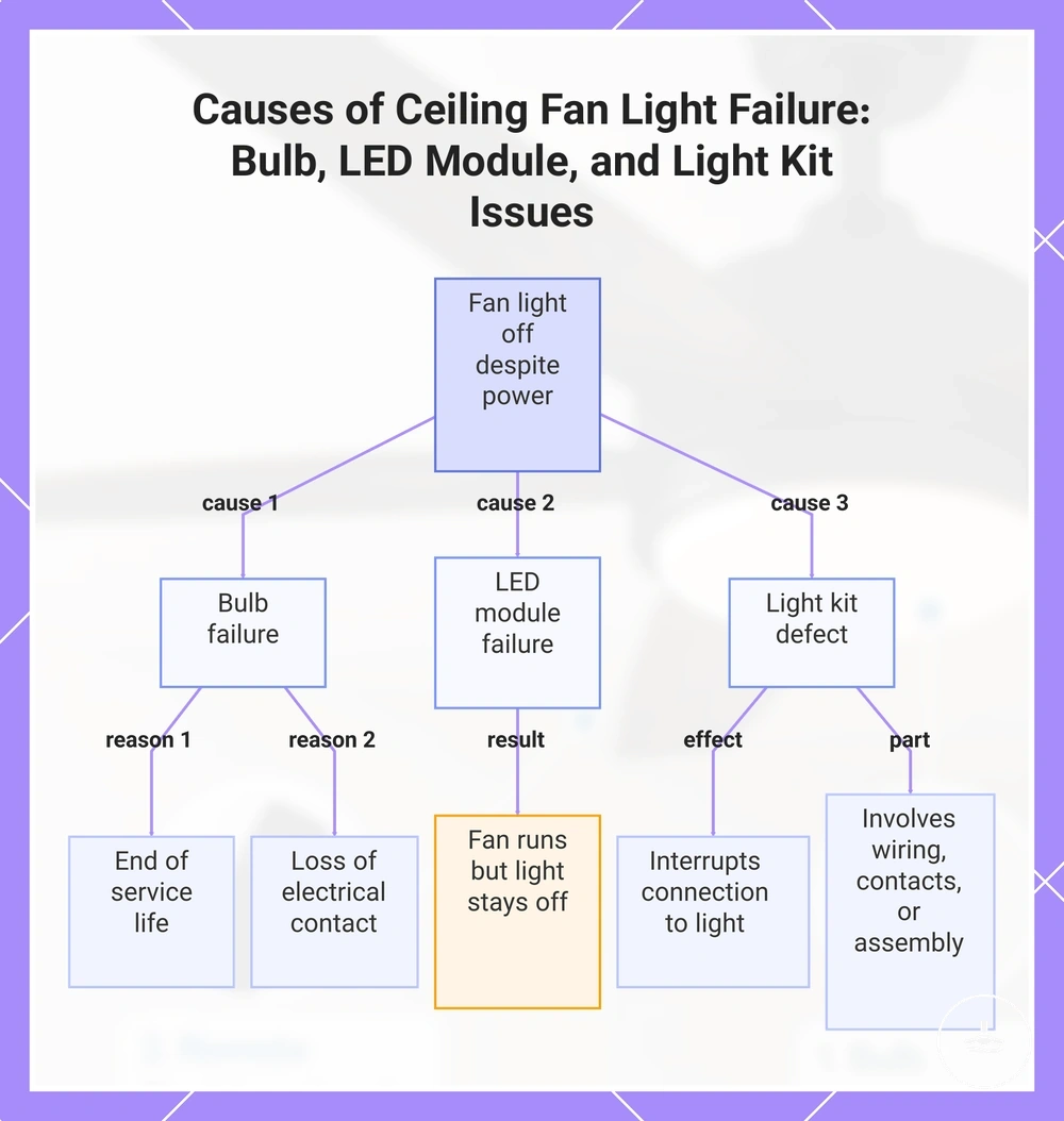
If the fan motor operates but the light remains off, the light-producing branch becomes more likely. The correct first check depends on whether the fan uses a replaceable bulb or an integrated LED assembly; those designs are not serviced in the same way.
| Lighting part | Attribute / role | Failure value or condition | Practical implication |
|---|---|---|---|
| Replaceable bulb | Creates light in a user-replaceable socketed design | A failed lamp or poor lamp-to-socket contact can produce complete light loss | With power isolated and the lamp cool, try a known-good bulb that matches the fixture's required base, type, and rating. |
| Integrated LED module | LED board built into the light assembly, commonly used with a dedicated driver | Module or driver failure can cause no light, flicker, or intermittent output | Replacement is model-specific; the compatible LED module, driver, or complete light kit may be the service part. |
| Light kit / socket assembly | Connects the light source to the fan's lighting circuit | Socket, contact, connector, or internal wiring faults can interrupt the branch | If a known-good compatible bulb does not restore a socketed light, avoid random part replacement and move to model-specific inspection or service. |
A bulb swap is only a valid first test when the design actually uses a user-replaceable bulb. Integrated LED fans skip that step and should be diagnosed as a module/driver/control system instead.
The chart below shows the three light-side fault categories and how each can lead to complete light loss.
Wiring Problems and Loose Electrical Connections in Ceiling Fan Light Circuits
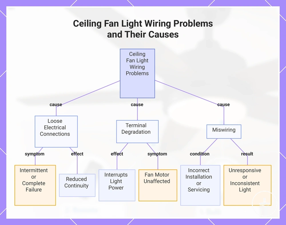
Wiring faults can interrupt only the lighting branch even when the fan motor still works. Loose connectors, damaged terminals or conductors, and incorrect wiring are therefore important when the fault is intermittent, began after installation or servicing, or persists after user-level light-source and control checks. For installation context, see wiring requirements.
| Wiring condition | Typical effect | What it means for the next step |
|---|---|---|
| Loose connector or terminal | Intermittent light, loss of light after vibration, or complete loss of the lighting branch | Do not probe or tighten energised wiring. If the connection is inside fixed wiring or a closed electrical enclosure, use qualified service. |
| Damaged terminal or conductor | Unreliable continuity and potentially heat, discolouration, or loss of power | Visible electrical damage is a stop condition rather than a cue for live testing. |
| Incorrect wiring | The light may never operate correctly, may respond to the wrong control, or may fail after installation changes | Compare the installation with the manufacturer's wiring information; fixed-wiring correction should be handled according to local electrical requirements. |
The chart below groups the main wiring fault types; the diagnostic table adds the symptom and safe escalation boundary.
Internal Component Failures Including Capacitor, LED Driver, and Light Control Module
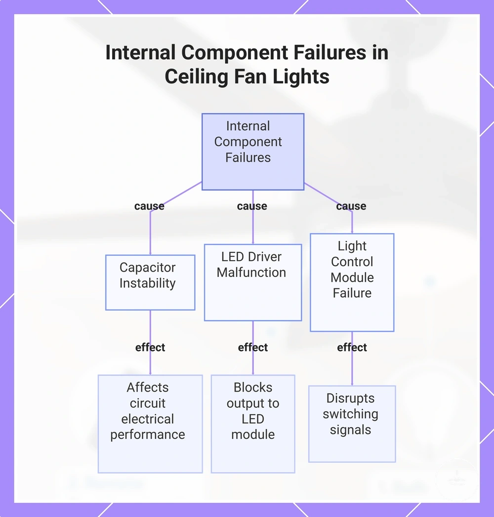
After the common supply, user controls, and user-replaceable light source have been checked, the fault may lie in an internal receiver, light control module, or LED driver. A capacitor needs a more careful interpretation because its function depends on the fan design.
| Component | Usual role | Light-failure interpretation | Decision |
|---|---|---|---|
| LED driver | Converts and regulates electrical power for an integrated LED module | A failed or unstable driver can produce no light, flicker, intermittent output, or delayed start | Use a compatible model-specific driver/module/light-kit solution rather than a generic replacement. |
| Light control module / receiver | Switches or regulates the lighting circuit and may interpret remote or smart-control commands | The fan can still run while the light command or lighting channel fails | Rule out handset battery, pairing, and other user controls first; internal module service may then be required. |
| Capacitor | Role is model-dependent; in many AC ceiling fans, capacitors primarily serve motor start/run or speed-control functions | A light-only failure should not automatically be blamed on the fan motor capacitor. A capacitor is relevant to the light only when the model's circuit actually uses one in the lighting/control path. | Use the model wiring diagram and qualified service rather than replacing a capacitor by assumption. |
The practical distinction is component function: an integrated LED driver and a light-control channel have a direct lighting role, while a common motor capacitor usually points more strongly to motor behaviour than to an isolated light fault.
The chart below illustrates the internal component categories; use the table above to keep their electrical roles distinct.
Step-by-Step Troubleshooting Process for Diagnosing Ceiling Fan Light Failures
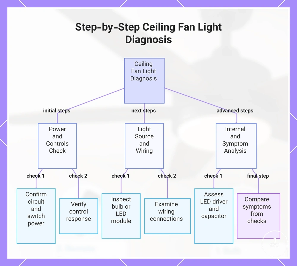
Diagnose the failure from the least invasive evidence first, then escalate only when the next check requires access to internal electrical parts. Routine cleaning and maintenance can also make visible damage or looseness easier to notice before a fault develops.
- Apply the safety stop first. If there is sparking, scorching, a burning odour, overheating, exposed wiring, a loose fixture, or a breaker that keeps tripping, stop using the fan and arrange qualified assessment.
- Separate a whole-fan fault from a light-only fault. If both fan and light are dead, check the common breaker and wall control status. If the fan runs, continue along the lighting branch.
- Compare the available controls. Try the normal wall control, pull chain, remote, or smart-control path that the model provides. For a remote, check the handset battery and follow the model's pairing instructions.
- Check the light source only if it is user-replaceable. Isolate power before handling the lamp, then try a known-good compatible bulb. An integrated LED does not have a normal bulb-swap step.
- Stop before unsafe wiring work. If diagnosis now depends on opening fixed wiring, probing live conductors, or correcting terminals, move to a licensed electrician or appropriate qualified service rather than testing energised parts.
- Use the symptom and model design to narrow internal parts. For integrated LEDs, consider the driver/module path; for remote-controlled lights, consider the receiver/light-control channel; do not replace unrelated motor components simply because the light is off.
Decision rule
Each completed check should narrow the next branch. Do not replace multiple parts at random when the symptom can first distinguish supply, control, light source, wiring, and internal electronics.
The existing chart visualises the same troubleshooting sequence from initial power and symptom checks to internal-component assessment.
Safety Checks and When to Call an Electrician for Ceiling Fan Light Problems
Electrical symptoms change the troubleshooting boundary. User-level observations such as control status, remote batteries, and a compatible replaceable bulb are different from opening fixed wiring, testing live voltage, or repairing internal electrical connections. Review the safety checklist before deciding whether further inspection is appropriate.
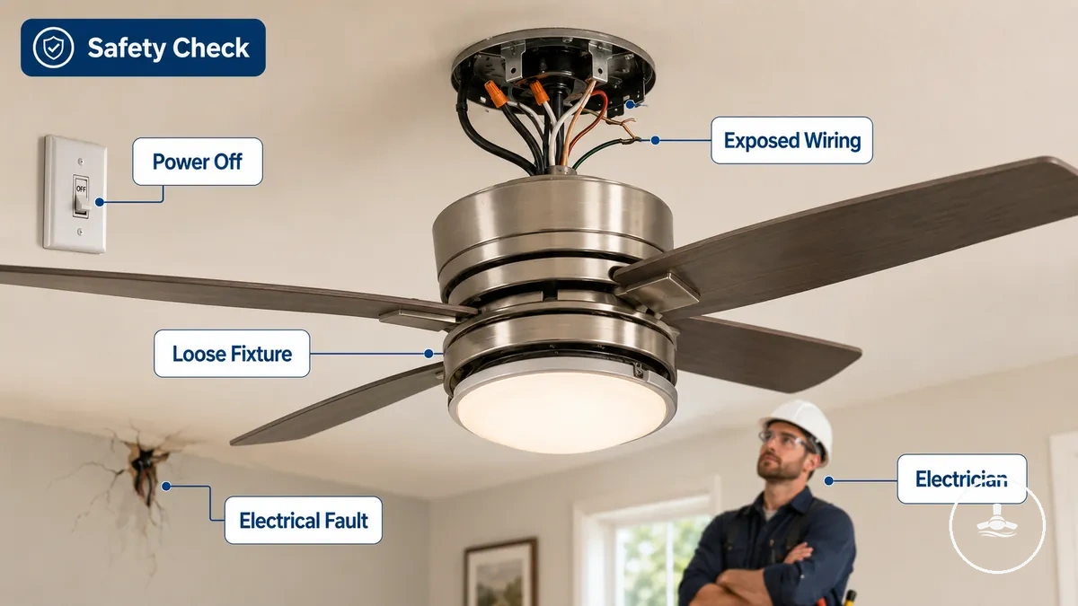
- Sparking, scorching, a burning odour, or overheating: stop using the fixture. Isolate power at the switchboard if it is safe to do so and arrange qualified electrical assessment.
- A breaker that trips again: do not keep resetting it. Repeated tripping indicates a fault that should be investigated.
- Exposed or damaged conductors: do not touch them or continue operating the fan; keep the circuit isolated and seek qualified help.
- A loose or unstable fan or light kit: stop operation until the mounting and electrical condition have been checked.
- Diagnosis requires fixed-wiring access or live measurement: use a licensed electrician or appropriate qualified service in accordance with local requirements and the manufacturer's instructions.
- Simple user-level checks do not restore the light: move to model-specific service information rather than opening the fixture and testing by trial and error.
The safest stopping point is before troubleshooting becomes electrical repair. If you cannot verify the next step without accessing internal wiring or energised components, professional assessment is the appropriate next action.