Ceiling Fans with Lights Installation Requirements and Limits
A ceiling fan with light is installation-ready only when four conditions are verified: suitable structural support, sufficient blade-and-light clearance for the specific fan and room, a compatible mounting method, and an electrical/control arrangement that meets the product instructions and applicable local requirements. Power at an existing light point is not proof that the point is fan-ready; unresolved support, fixed-wiring, or compliance questions should be assessed by the appropriate qualified trade professional.
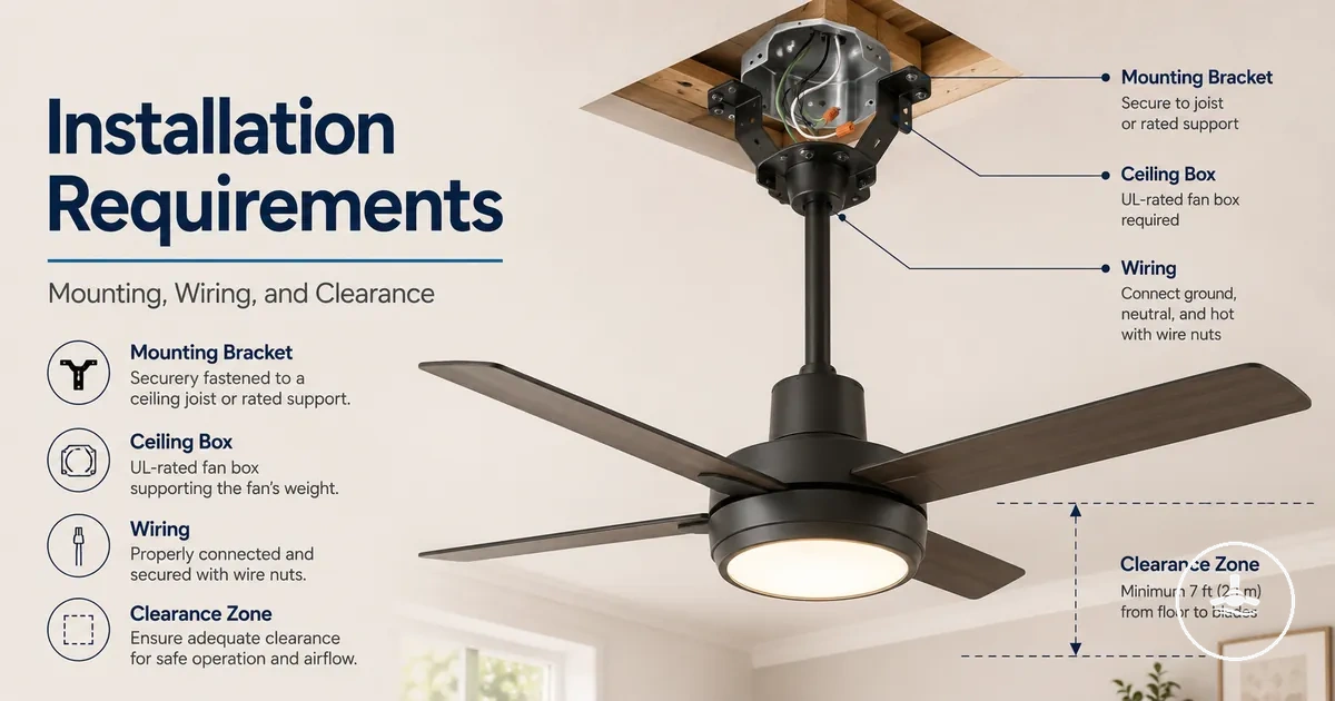
Fan-ready installation gate
Mark a prerequisite only when it has actually been confirmed for the specific fan, room and mounting point. The result identifies planning gaps; it does not certify structural capacity or electrical compliance.
If a prerequisite cannot be verified from the fan documentation or by safe inspection, treat it as unresolved rather than assuming it is acceptable.
An existing light point can be a useful starting location, but the fan creates a moving structural load and may need a different control arrangement from the old light. Where a support box or mounting assembly carries the fan, it must be suitable for that purpose and securely connected to structural framing or another approved support method.
Clearance is a finished-installation condition: check the complete blade sweep, motor/canopy space, light drop, door and cabinet swing, furniture, and usable headroom against the exact fan's instructions and any applicable local requirements. A centred ceiling point is not automatically a safe fit.
Use the readiness gate below to organise the decision before installation. It is a planning aid rather than a structural or electrical compliance certificate; if any prerequisite is unverified, resolve it first. For broader product-selection context, use the ceiling fans with lights hub.
Installation conditions before replacing a light fixture
Replacing a light fixture with a ceiling fan with light is suitable only when the existing point passes checks for structural support, mounting compatibility, room clearance, electrical/control suitability, and the condition of the ceiling and wiring. An existing electrical supply is therefore only one part of readiness.
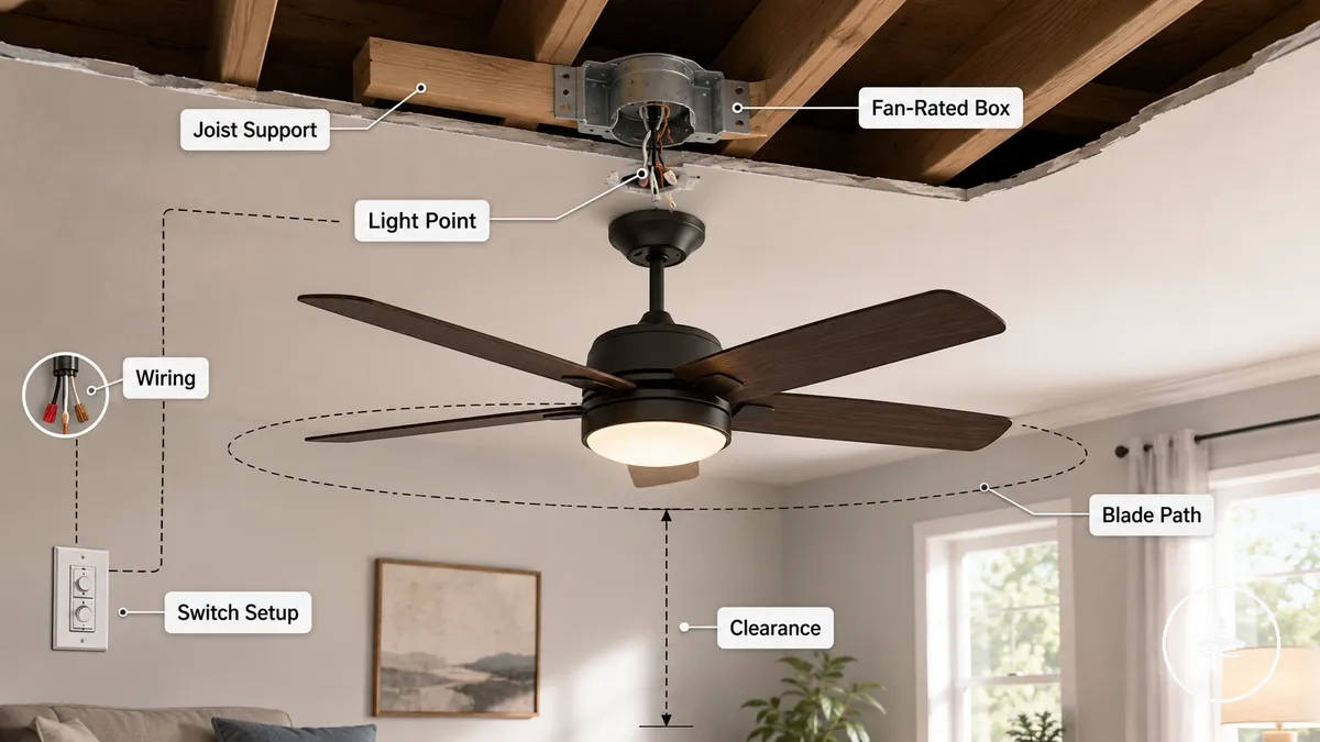
Where a ceiling box or support assembly carries the fan, it should be suitable for fan loading and securely fixed to structural framing or another approved support method. The chosen controls must suit the fan and light, while the completed blade path and light drop must remain clear.
Use this pre-installation checklist before treating the existing light point as fan-ready:
- Fixture position: The installed blade sweep and light drop remain clear of walls, doors, cabinets, furniture and normal movement through the room.
- Support assembly: Any box, brace or support assembly that carries the fan is specifically suitable for fan support and installed according to its rating or instructions.
- Structural fixing: The load path reaches a sound joist, brace or other approved structural fixing; ceiling lining alone is not assumed to be sufficient.
- Control setup: The selected wall control, remote receiver or combined control method is supported by both the fan and the available wiring/control arrangement.
- Ceiling condition: The mounting surface and surrounding structure are sound enough for the specified mounting method, with no unresolved damage or movement.
- Access for verification: The support and fixing method can be verified rather than inferred from the presence of the old light fitting.
- Room clearance: The final fan dimensions and mounting drop satisfy the fan manufacturer's stated clearances and any applicable local requirements.
Existing wiring, switch control, and fixture location limits
Existing wiring, controls and fixture position determine whether the light point can support the intended fan-and-light operation. Wires being present does not establish control compatibility, wiring condition or structural readiness.
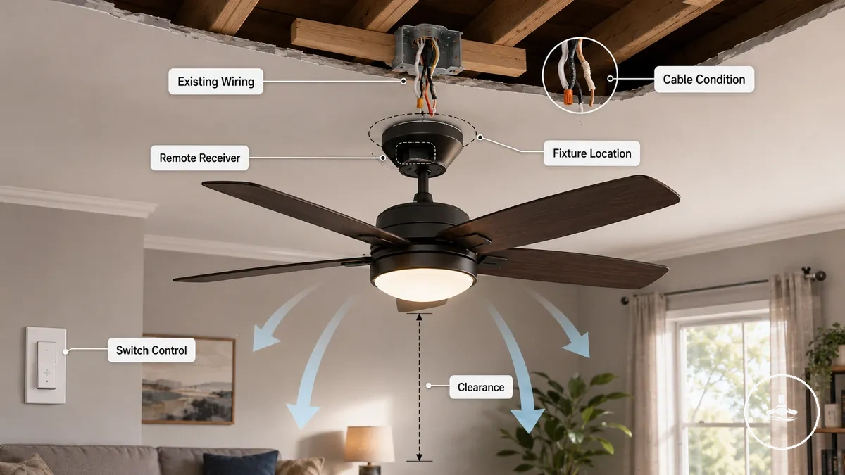
Assess each factor by the condition that must be true before it can be treated as ready:
| Factor | Ready condition | If the condition is not met |
|---|---|---|
| Wall control | The installed switch/control arrangement is compatible with the selected fan and the intended shared or independent fan/light control. | Use a supported control method or have any required fixed-wiring changes assessed by an authorised electrician. |
| Remote receiver | The receiver is specified as compatible with the fan/control system and fits within the available canopy space without forcing components. | Choose a compatible control configuration; canopy space cannot be assumed from the presence of an existing light point. |
| Fixed wiring | Wiring condition and required conductors/control arrangement are known to be suitable for the planned installation. | Damaged, old or uncertain wiring should be assessed before connection work proceeds. |
| Fixture position | The completed blade sweep and light drop satisfy the fan's installation limits for the actual room. | A powered location that conflicts with clearance is not an acceptable fan location. |
| Nearby obstructions | Doors, cabinets, furniture and ceiling features stay outside the required operating envelope. | Change the fan size, mounting method or location rather than accepting a contact zone. |
Ceiling structure and fan-rated box requirements
A ceiling fan creates a moving load, so the mounting point needs a verified structural support path, not merely an electrical connection. Suitability depends on the support method, framing, bracket, fasteners and the specific fan's mounting instructions.
A fan-rated support box may form part of that load path where such a system is used, but the box is only as suitable as its rating and structural attachment. In other installations, the mounting bracket may be fixed to a joist, brace or another manufacturer-approved support. A light-duty junction box or ceiling lining must not be assumed to carry fan weight and vibration.
Do not infer structural capacity from appearance, age or the fact that a light was previously installed. If the framing, fixing method or support rating cannot be verified, keep the support status unresolved and obtain an appropriate structural or trade assessment.
| Support element | Required state or value | Practical implication |
|---|---|---|
| Structural fixing | Sound joist, brace or other approved support capable of carrying the fan through the specified mounting method. | This is the primary load path; decorative ceiling lining is not a substitute for verified structural support. |
| Support box, when used | Rated or approved for fan support and installed according to its rating/instructions. | An ordinary light-only box does not establish fan suitability. |
| Mounting bracket | Compatible with the fan and the verified support method. | A bracket transfers load; it cannot compensate for weak or unknown structure. |
| Fasteners | Manufacturer-specified or otherwise approved for the bracket, substrate and support method, and securely installed. | Generic or mismatched hardware can invalidate an otherwise suitable support path. |
| Existing mounting point | No unresolved looseness, damage or uncertain concealed fixing. | Movement or uncertainty is a reason to stop and assess the support before installation. |
| Ceiling surface | Stable and compatible with the installation detail, but not treated as load-bearing unless the system is specifically designed that way. | Surface condition matters for fit; structural capacity must come from the approved support method. |
Junction box support and ceiling joist attachment
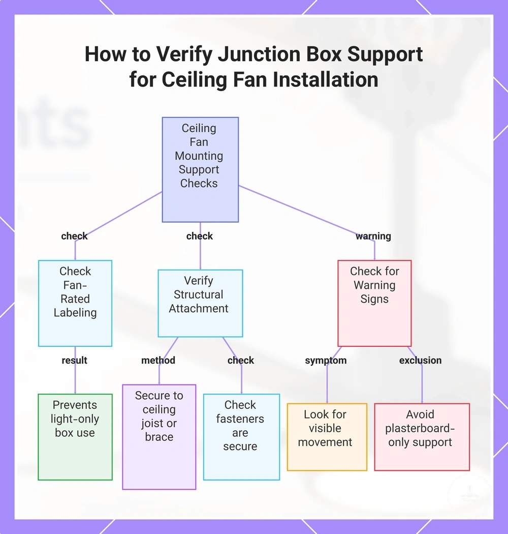
If a junction or support box forms part of the fan's mounting system, it should be identified as suitable for fan support and securely attached to structural framing or an approved brace. The box label alone is not enough if the attachment method is loose, damaged or unknown.
Older boxes and concealed fixings deserve extra caution because visible appearance does not reveal the support path. Use the following checks to distinguish a verified fan-support point from an ordinary light connection.
- Rating or identification: Where the box carries fan load, its marking or documentation confirms that use.
- Joist or brace attachment: The box/support is securely connected to structural framing or an approved brace.
- Fasteners: Fixings are appropriate to the support method and show no looseness or damage.
- Movement: The mounting point has no unexplained movement; movement is a reason for assessment before mounting the fan.
- Ceiling-lining-only support: Plasterboard or other ceiling lining is not treated as the sole structural support unless the complete system is specifically approved for that use.
The illustration below summarises the support path to verify before a ceiling point is treated as fan-ready.
Mounting bracket and hardware requirements
The mounting bracket transfers the fan assembly to the verified support point. Bracket strength does not compensate for weak or unverified ceiling support, so bracket compatibility is checked only after the support path is established.
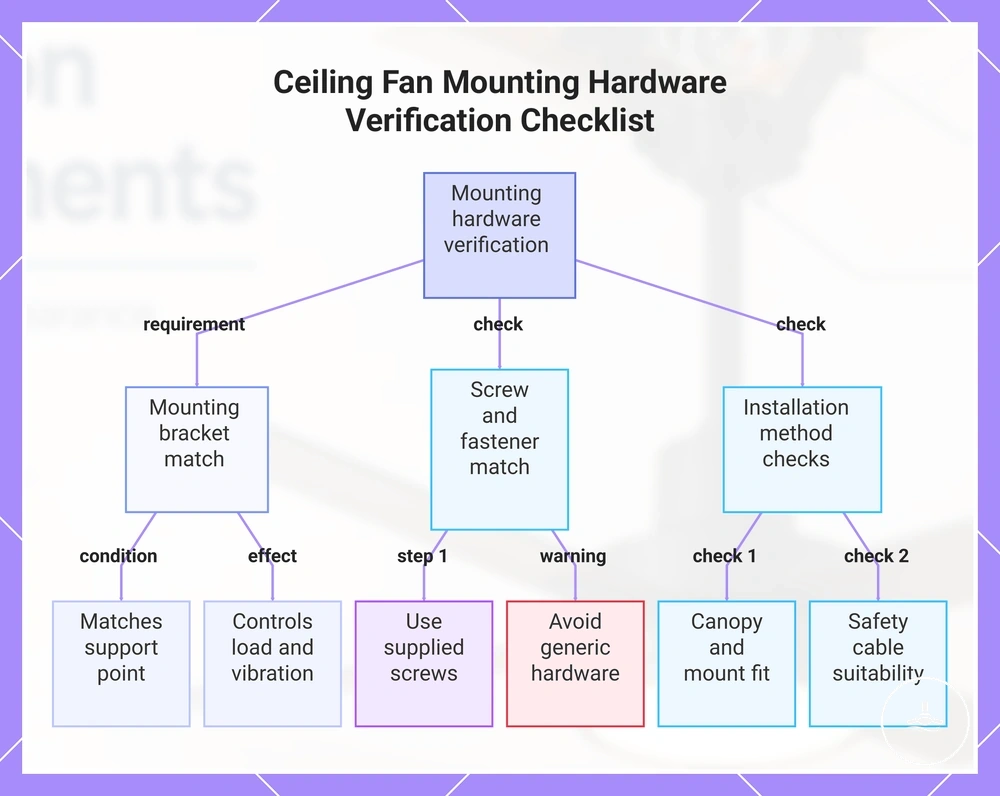
Hardware must match the fan, canopy and mounting method. Flush, downrod and angled installations can use different interfaces; manufacturer-supplied or manufacturer-specified parts should not be treated as interchangeable with generic hardware without confirmation.
Verify these mounting-hardware relationships before installation:
- Mounting bracket: The bracket is the correct type for the fan and verified support point.
- Screws and fasteners: Use the supplied or specified fasteners for the actual support method; do not assume generic fasteners are equivalent.
- Canopy: The canopy seats correctly over the bracket and leaves the required space for wiring and any approved receiver.
- Flush mount or downrod: The hardware matches the selected mounting interface; the two methods are not automatically interchangeable.
- Safety cable: Use a safety cable only where the fan design or instructions provide for it, and attach it as specified.
The illustration below provides a compact compatibility check for bracket fit, fasteners and mounting method.
Clearance limits for safe fan and light placement
Clearance is acceptable when the complete installed envelope—blade sweep, motor/canopy, light and mounting drop—fits the room without contact risk or unusable headroom. Room centre alone is not a clearance value.
Use the exact fan's installation instructions for model-specific minimum spacing and combine them with any applicable local requirements. The table below closes each clearance attribute with a practical pass condition rather than assuming one generic distance suits every fan.
Measure the actual room and final hanging dimensions before installation; if a required model-specific clearance cannot be verified, treat that dimension as unresolved.
| Fan or room element | Clearance value/condition | Decision rule |
|---|---|---|
| Blade sweep to walls or fixed objects | At least the model-specific minimum clearance, with the entire rotating path unobstructed. | If the required spacing is unavailable, change fan size or location. |
| Lowest blade/light point | Finished height satisfies the fan instructions and applicable requirements while preserving usable headroom. | A deeper light kit or longer drop can make an otherwise suitable location unacceptable. |
| Motor, canopy and ceiling | Spacing and ventilation follow the fan's stated mounting limits for the selected flush/downrod arrangement. | Do not force a low-profile installation the fan does not support. |
| Doors and cabinet doors | The full opening arc remains outside the blade sweep and light envelope. | Any overlap is a placement conflict, even if the fan is centred. |
| Furniture and tall objects | No normal-use object enters the contact zone; nearby large objects should not crowd airflow around the fan. | Reposition furniture or revise the fan/location before use. |
For a broader pre-installation review, the weight and clearance safety checklist organises structural and room-clearance checks together.
Floor, wall, and ceiling clearance checks
Floor, wall and ceiling checks compare the fan's specified operating envelope with the real room dimensions. The useful value is the remaining clearance after the fan and light are fully installed, not the empty-room distance before mounting.
Check each contact zone against the exact fan dimensions and instructions:
- Below the fan: Confirm the lowest blade and light point preserve the required and practical headroom for the room.
- Walls and fixed features: Measure from the outer blade sweep to nearby walls, beams and other fixed features and compare with the model-specific minimum.
- Ceiling and canopy: Confirm the selected mount provides the ceiling spacing required by the fan design and does not obstruct the canopy or motor housing.
- Light depth: Include the full light-kit depth in the finished hanging height rather than checking blade height alone.
- Doors and cabinets: Open them through their full normal travel and keep that path outside the fan and light envelope.
- Furniture: Check tall furniture and movable objects in their normal-use positions so they do not create a contact zone or crowd the airflow path.
Low ceiling and flush mount installation limits
A flush or hugger-style mount can reduce fan drop, but reduced drop does not remove structural, blade-clearance or electrical requirements. The fan must explicitly support the chosen low-profile mounting method.
Low-ceiling fit is a trade-off between finished headroom and the fan's required spacing from the ceiling. Some designs maintain better airflow with a downrod, so the shortest physical drop is not automatically the best functional choice.
Compare mounting approaches by their fit condition rather than by drop alone. For related room-specific guidance, see low ceiling installation limits.
| Mounting approach | Main benefit | Best-fit condition / limit |
|---|---|---|
| Flush or hugger mount | Minimises the distance the fan projects below the ceiling. | Use only when the fan is designed for this mounting mode and its required blade-to-ceiling spacing plus light headroom can be met. |
| Compatible short downrod | Can retain more designed airflow space while limiting total drop. | Suitable only when the fan, canopy and ceiling height support that downrod length and all clearances remain compliant. |
| Deeper light kit on any mount | Adds light output/fixture depth but no clearance benefit. | Include the full light depth in finished headroom; a light kit can be the limiting dimension in a low room. |
Downrod and sloped ceiling installation conditions
Downrod and sloped-ceiling suitability depends on the fan's permitted ceiling angle, compatible angled-mount hardware, structural support and the final hanging envelope. The fan should hang in the orientation specified by the manufacturer without the canopy, downrod or blades conflicting with the slope.
There is no reliable universal downrod length for every sloped room. Choose the drop from the exact fan's mounting options, ceiling geometry, blade sweep and finished light/headroom requirements.
Use this compatibility checklist. For detailed slope-specific planning, see sloped ceiling installation needs.
- Ceiling angle: The slope is within the fan or compatible adapter's stated range.
- Angle adapter: Any slope/angle adapter is approved for the fan, canopy and mounting method.
- Downrod: The selected downrod is an approved compatible length/diameter for the fan and keeps the blade plane and clearances within specification.
- Canopy: The canopy can seat correctly at the ceiling angle without interference.
- Finished hanging height: The combined downrod, fan body and light kit preserve the required blade and light clearances.
Electrical readiness for fan and light operation
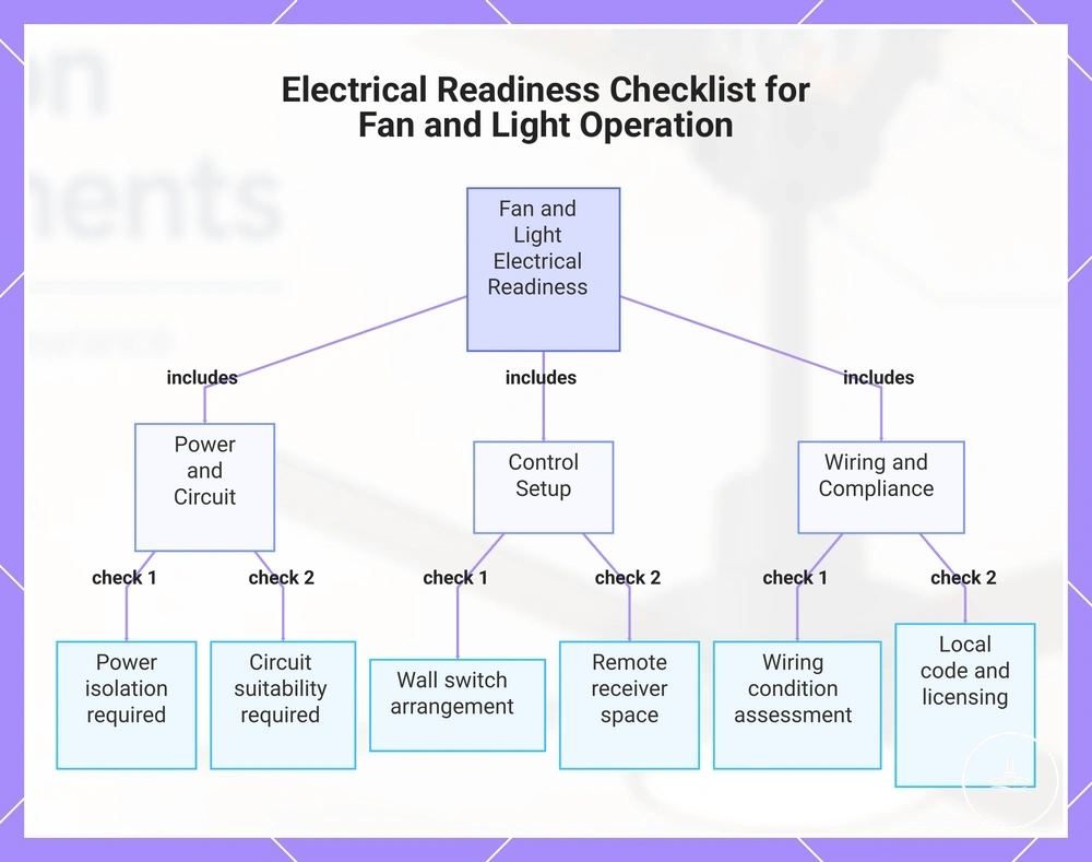
Electrical readiness is a separate gate from structural readiness. The fan and light need a compatible supply and control arrangement, sound fixed wiring, suitable space for any approved receiver, and connection work that follows the product instructions and applicable state or territory requirements.
An existing light circuit may support shared control, independent fan/light control, or a receiver-based arrangement depending on the installed wiring and the fan design. Do not infer control capability from the old light switch alone.
Use this checklist for planning only. Fixed-wiring alterations, testing or compliance work should be completed by a licensed or otherwise authorised electrician where required by local rules.
- Supply isolation: Electrical work starts only after the relevant supply is isolated and de-energised status is verified by an appropriately competent/authorised person.
- Circuit suitability: The circuit, protective device and connected load are known to be suitable for the specified fan and light; unknown capacity is an electrician-assessment item.
- Control method: The wall control, remote or combined arrangement is supported by the fan and the available control wiring.
- Remote receiver: Any receiver is the correct compatible unit and fits within the canopy in the position allowed by the manufacturer.
- Fixed-wiring condition: There is no unresolved damage, deterioration or uncertainty in the wiring used for the installation.
- Local licensing and compliance: Any work that local law reserves for licensed electrical workers is assigned accordingly; requirements can vary by Australian state or territory and installation type.
The illustration below groups the same readiness checks into supply/circuit, control, wiring and compliance categories.
Power isolation, circuit load, and code checks
Power isolation, circuit suitability and compliance checks are safety gates before fixed-wiring connection work. They reduce the risk of electric shock, unsuitable loading and non-compliant work without turning this page into an electrical test procedure.
The exact testing method, licensing obligation and wet-area requirements depend on the installation and jurisdiction. Where these conditions are not already documented and verified, use an appropriately licensed or authorised electrician.
- Isolation and verification: The relevant circuit is isolated and de-energised status is verified before electrical work proceeds.
- Circuit capacity: Circuit/protective-device suitability is confirmed for the fan and light load; uncertainty is resolved by an electrician rather than by assumption.
- Wiring condition: Damaged, deteriorated or unidentified conductors are a stop condition for DIY assessment.
- Damp or wet location: The fan/light equipment and installation method are confirmed suitable for the location and any applicable zone or ingress-protection requirements.
- Compliance and licensing: The work method and person performing it satisfy applicable state/territory electrical rules and any required certification.
Light wiring, remote receivers, and wall switches
The control method determines what the existing wiring must support and how the fan and light can be operated. Treat the wall switch, receiver, light driver and fan electronics as one compatibility chain, not as independent interchangeable parts.
For detailed wiring-layout context, see wiring requirements for fan lights. The matrix below shows the condition that must be true for each control approach.
| Control approach | Required condition | Practical result or limit |
|---|---|---|
| Separate wall controls | The fan design and installed control wiring support independent fan and light channels. | Fan and light can be controlled independently only when the complete wiring/control arrangement supports it. |
| Shared wall switch | The selected fan/control system is designed to operate from the available switched supply. | The wall switch may energise both functions; separate operation then depends on the fan's supported internal/remote controls. |
| Remote receiver | The receiver is specified for the fan, connected through an approved arrangement, and physically fits the canopy. | Remote control is feasible only when both electrical compatibility and canopy space are satisfied. |
| Light dimming | The light source/driver and the chosen dimming control are explicitly compatible. | An ordinary or incompatible dimmer can produce flicker, poor control or unsafe/unsupported operation. |
| Control configuration | The selected method matches the actual wiring, fan electronics and manufacturer instructions. | Choose the control plan from verified compatibility rather than assuming the old light switch dictates the new setup. |
Installation sequence for a ceiling fan with light
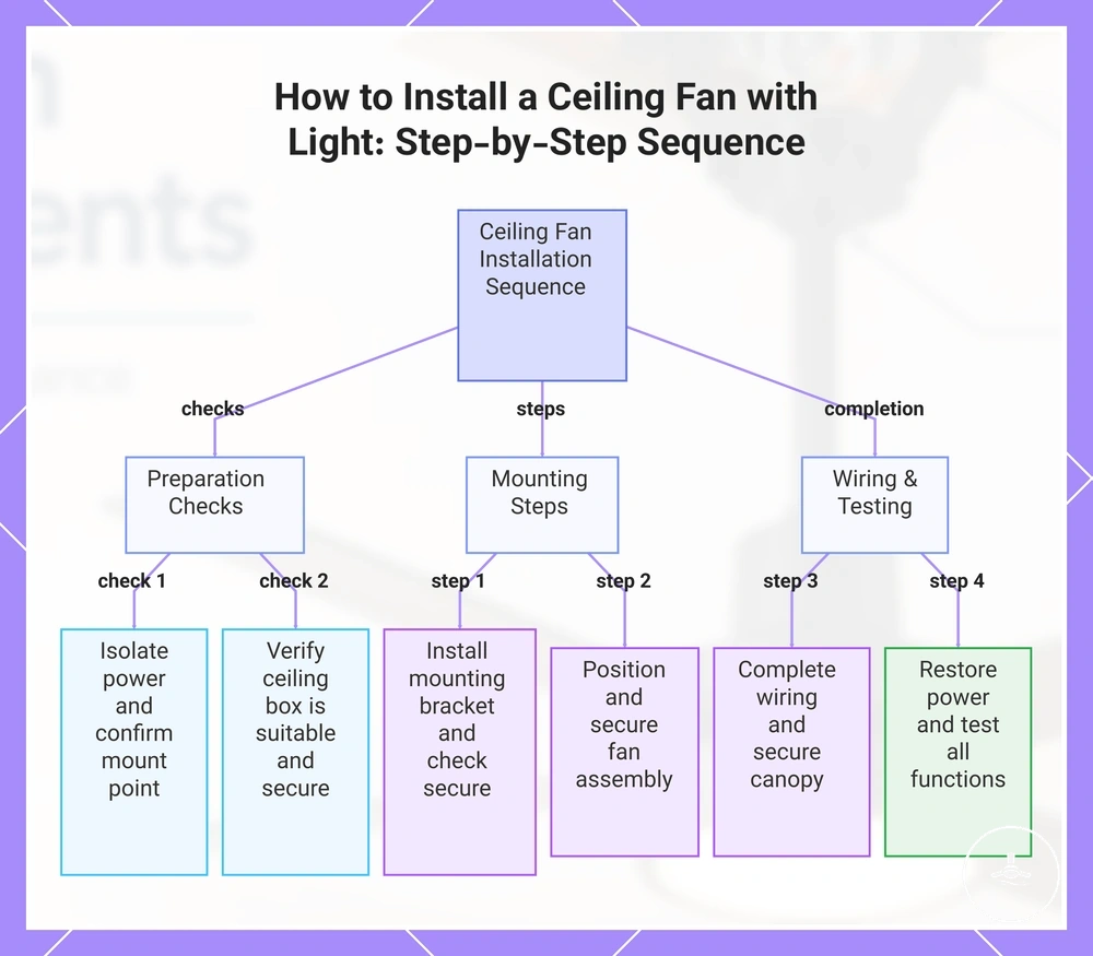
The installation sequence begins only after the readiness gates for support, clearance, mounting and electrical/control planning are resolved. The order matters because later assembly cannot correct an unsuitable support point or an unverified electrical condition.
Use the fan manufacturer's instructions as the controlling procedure. Electrical connection, testing or fixed-wiring work must be handled by a licensed/authorised electrician where required.
- Verify prerequisites: Confirm structural support, mounting compatibility, finished clearances and the electrical/control plan before removing or fitting components.
- Make the work area electrically safe: Have the relevant supply isolated and verified in the manner required for the work and jurisdiction before any fixed-wiring activity.
- Prepare the verified support point: Expose and confirm the mounting support and surface condition without reusing unknown light-fixture hardware by default.
- Install the specified mounting hardware: Fit the correct bracket, downrod/flush hardware and fan body using the manufacturer's specified support and fastener method.
- Complete the electrical/control work: Have the fan/light wiring, control and any receiver connected and checked under the product instructions and applicable licensing rules.
- Fit blades and light components: Complete the mechanical assembly, then recheck fasteners, blade sweep, light drop and canopy fit.
- Commission and observe: After all checks are complete, test fan speeds, light/control functions, wobble and unusual noise; stop use and investigate abnormal behaviour.
The illustration below visualises this prerequisite-first sequence from planning through commissioning.
Removing the old fixture and preparing the ceiling box
Removing the old light fixture is useful only when it is part of a safe, permitted inspection path. The objective is to expose the mounting point so the support method and wiring condition can be identified, not to assume the old hardware can carry the fan.
If local rules reserve the electrical work for a licensed electrician, or if isolation, wiring condition or concealed support cannot be verified safely, professional assessment comes before further preparation.
- Confirm who is authorised to do the work: Resolve applicable electrical licensing requirements and safe isolation before the old fixture is disturbed.
- Expose the mounting point safely: Remove the old fitting only within those safety and licensing limits so the box/support and surrounding ceiling can be inspected.
- Identify the structural support path: Verify whether the mounting point is secured to a suitable joist, brace or approved fan-support system.
- Assess visible wiring condition: Treat damage, deterioration, unidentified wiring or uncertainty as an electrician-assessment condition rather than continuing by guesswork.
- Prepare the surface for the specified mount: Only after support and electrical conditions are resolved, ensure the mounting surface is unobstructed and compatible with the fan's bracket/canopy.
Mounting, wiring, assembling, and testing the fan
Mounting, wiring, assembly and testing should follow the fan manufacturer's sequence after the ceiling point has been verified. The main relationships are support → bracket → fan body, electrical/control plan → connection/receiver, and complete assembly → functional test.
Do not use successful fan operation as proof that the structure or electrical work is compliant. A fan that runs can still have an unsuitable support, clearance or wiring condition.
- Secure the specified bracket: Attach the compatible bracket to the verified support using the specified fixing method and confirm there is no unexplained movement.
- Seat the motor/fan body: Position the fan body exactly as the mounting design requires before it is treated as mechanically supported.
- Complete electrical and receiver work: Use the approved wiring/control configuration and receiver placement; licensed/authorised electrical work stays with the appropriate electrician.
- Close the canopy without forcing components: Confirm wiring and any receiver fit within the permitted space and that the canopy seats correctly.
- Fit blades and the light kit: Use the supplied/specified hardware, then recheck the full blade sweep and final light hanging height.
- Commission the completed installation: After authorised electrical checks and full assembly, verify normal fan speeds, light/control operation, wobble and unusual noise; stop use if abnormal conditions appear.
Installation mistakes that create unsafe or poor fit
Installation mistakes usually come from an open requirement being treated as if it were verified. The most important failures involve support, clearance, mounting hardware, wiring assumptions and control compatibility.
Mechanical and electrical symptoms can overlap, so a symptom should trigger the relevant check rather than a guessed repair. The matrix links each mistake to the affected attribute, likely consequence and decision.
Wobble, movement, unusual noise, flicker or inconsistent control can have more than one cause. If the cause is not obvious from safe external checks, stop using the fan and obtain appropriate trade assessment.
| Mistake | Affected attribute | Possible consequence | Correct decision |
|---|---|---|---|
| Light-only or unsuitable support used for fan load | Structural support | Movement, loosening or unsafe load transfer may occur. | Verify a fan-suitable structural support path before use. |
| Weak or unverified framing/fixing | Stability | Vibration or mounting movement may increase. | Have the support assessed and corrected before operation. |
| Mounting height/drop not checked | Clearance | Reduced headroom or contact zones can result. | Recalculate the finished fan-and-light envelope using the actual mount. |
| Blade sweep not checked | Collision clearance | Walls, doors, cabinets or furniture can enter the rotating path. | Change location, fan size or room arrangement before use. |
| Loose or mismatched hardware | Mounting security | Wobble or movement may appear. | Use the specified compatible hardware and recheck mechanical security. |
| Existing wiring assumed compatible | Electrical/control suitability | Fan/light operation can be unreliable or unsafe. | Have the actual wiring/control arrangement verified before connection or continued use. |
| Control or dimmer mismatch | Control compatibility | Flicker, limited functions or abnormal control behaviour may occur. | Use only control equipment explicitly compatible with the fan/light system. |
Wrong box, weak support, and poor mounting height
Wrong support selection, weak fixing and poor mounting height are mechanical fit failures. They affect load transfer, movement and clearance, so they should be corrected at the requirement level rather than by trying to mask wobble or reduce fan speed.
Use these signs as prompts for inspection, not as single-cause diagnoses:
- Unsuitable support box or mounting point: If the support is not documented/identified for fan use or its structural fixing is unknown, do not treat it as fan-ready.
- Weak structural support: Movement at the support or reliance on ceiling lining alone requires structural assessment before operation.
- Loose bracket or hardware: Visible/measurable movement can contribute to wobble; verify the specified mechanical fixing rather than compensating elsewhere.
- Poor mounting height: Insufficient finished clearance means the mount/fan/location is a poor fit even if the fan operates normally.
- Excessive light drop: The light kit can become the lowest limiting dimension; include it in headroom and collision checks.
Wiring errors that affect the fan or light
Wiring and control faults can affect fan operation, lighting, remote response and electrical safety. Interpret symptoms as possible indicators, not proof of one specific cause, because mechanical, control and supply problems can overlap.
If a symptom points to fixed wiring, damaged conductors, overheating, repeated protection-device operation or another concealed electrical issue, stop use and obtain electrician assessment.
| Observed issue | Possible electrical/control cause | What the symptom means | Next check |
|---|---|---|---|
| Intermittent fan or light operation | Loose connection or unstable control/supply path | A connection/control problem is possible and may carry safety significance. | Stop relying on the fixture until the connection and supply path are assessed as required. |
| Light flicker or abnormal dimming | Incompatible dimmer, driver or control method | Dimming compatibility is incomplete somewhere in the control chain. | Confirm the light/driver/fan documentation explicitly supports the chosen dimmer/control. |
| Unreliable remote response | Receiver incompatibility, placement/space issue, power/control issue or remote problem | Receiver placement alone is not a certain diagnosis. | Check documented compatibility and permitted receiver position before assuming a wiring fault. |
| Fan and light do not separate as intended | Shared-switch/control configuration differs from the intended arrangement | The installed control topology may not support independent operation. | Compare the actual control setup with the fan's supported wiring/control options. |
| Canopy will not close normally | Receiver or wiring arrangement exceeds available permitted space | Forcing components can create a poor installation. | Use only a compatible receiver/control arrangement that fits the canopy as specified. |
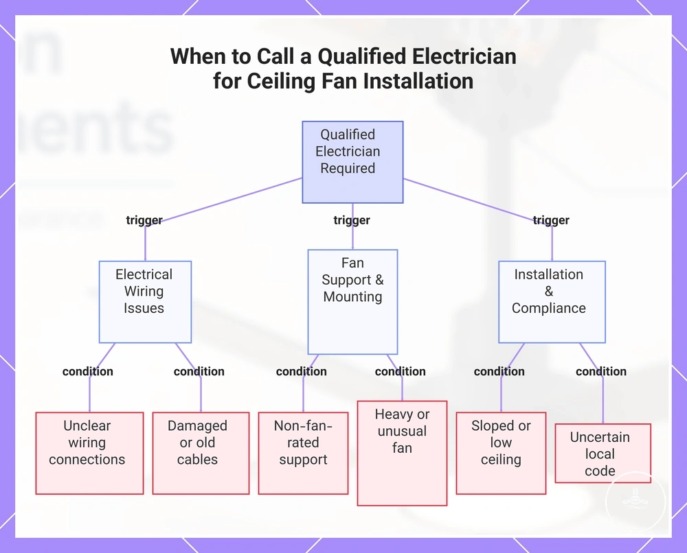
When a qualified electrician is required
Use a qualified, licensed or otherwise authorised electrician when the installation involves fixed wiring, when the circuit or wiring condition is uncertain, when electrical testing/compliance is required, or whenever applicable local rules reserve the work for licensed electrical workers. Structural uncertainty is a separate issue and may also require an appropriate installer, carpenter/builder or other trade professional.
Low or sloped ceilings, heavy fans and unusual mounting points do not automatically make the problem electrical, but they can create support or clearance questions that must be resolved before the electrician completes connection work.
Escalate according to the unresolved attribute rather than guessing through it:
| Unresolved condition | Why self-assessment stops | Appropriate escalation |
|---|---|---|
| Fixed-wiring alteration or new wiring is needed | Electrical connection methods and licensing/compliance requirements apply. | Licensed/authorised electrician as required by the jurisdiction. |
| Wiring is damaged, deteriorated, unidentified or otherwise uncertain | The condition cannot be established safely from appearance alone. | Licensed/authorised electrician. |
| Circuit capacity, protection, isolation verification or wet-area compliance is uncertain | These are electrical safety/compliance attributes, not product-fit guesses. | Licensed/authorised electrician. |
| Structural support path cannot be verified | Fan load transfer and framing suitability are unresolved. | Appropriate structural/installation trade professional; involve an electrician separately for electrical work. |
| Fan is unusually heavy or uses a specialised mounting system | Support and fastener requirements may exceed a routine mounting detail. | Manufacturer guidance plus an appropriate installer/structural trade; electrician for electrical scope. |
| Low or sloped ceiling creates mounting/clearance uncertainty | Geometry, support and compatible hardware must be resolved before installation. | Appropriate installer/trade professional; electrician if the solution also changes fixed wiring. |
| Local licensing or compliance requirement is unclear | The legal scope of who may perform the electrical work is uncertain. | Confirm the relevant state/territory requirement or use a licensed electrician. |
After a verified installation, maintenance after installation should include periodic cleaning, fastener/fixture observation and attention to new wobble, noise or control changes.
The illustration below summarises common conditions that should move the job from assumption to professional assessment.