Ceiling Fans with Lights Safety Checklist
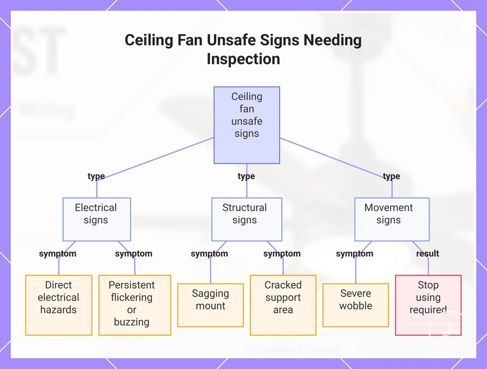
Before using a ceiling fan with light, check five risk areas: fan-rated support, unobstructed blade and head clearance, enclosed and undamaged wiring, an intact light kit, and stable operation without severe or increasing wobble. If support or wiring cannot be confirmed, or you notice sparks, a burning smell, repeated breaker trips, exposed conductors, a sagging or cracked mount, or severe wobble, stop using the fan and arrange qualified inspection; a visual checklist cannot certify concealed electrical or structural conditions.
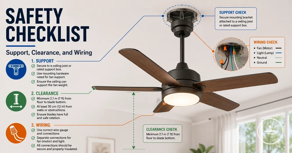
Five-point visible safety verifier
Choose the condition that best matches each area you can observe safely. The result separates routine visible checks from conditions that need verification or an immediate stop-use response.
This verifier is limited to safely observable conditions. It does not prove concealed ceiling support, electrical integrity, earthing continuity, or compliance with model-specific and local installation requirements.
Use the checklist as a condition-based screening tool, not as installation certification. The detailed sections below explain what each signal means and when to move from observation to manufacturer guidance, a licensed electrician, or another appropriately qualified inspection; for broader product context, see ceiling fans with lights.
Safety limits before installation or inspection
A safety checklist for ceiling fans with lights can flag visible warning signs, but it cannot verify concealed wiring, earthing continuity, ceiling framing, or the load rating of a hidden support. Keep inspection non-contact: if electrical isolation, mounting integrity, or any concealed condition cannot be confirmed safely, the checklist has reached its limit and qualified assessment is the appropriate next step.
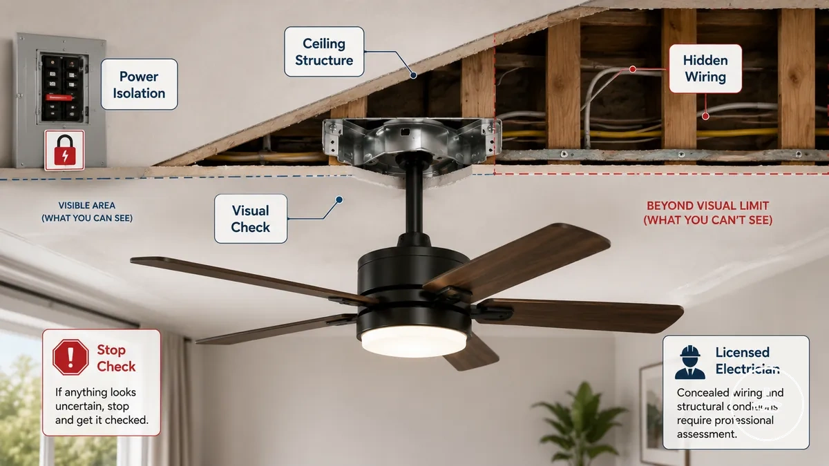
Before any close inspection, isolate the fan circuit at the switchboard where this can be done safely, and do not touch conductors or remove electrical covers. Visual checks can include the external canopy, visible mounting condition, blade clearance, light cover condition, and obvious damage; electrical testing or work on fixed wiring belongs with a licensed electrician. If the power state is uncertain, stop rather than attempting to prove isolation through contact.
Uncertain ceiling support, damaged mounting points, exposed conductors, or unclear control wiring cannot be cleared by appearance alone. In those cases, move from observation to professional verification and use the fan's instructions plus applicable local requirements as the decision boundary; the related installation limits page explains the broader installation context.
Stop the visual check when live parts may be exposed, the mounting point is unstable, or the electrical state is unclear. These are escalation conditions, not items to investigate by touching or dismantling the fan.
- Stop checking if live wiring or exposed electrical elements are suspected
- Do not proceed with contact when ceiling structure stability is unclear
- Avoid further inspection if mounting damage or looseness is visible
- Rely on a licensed electrician when hidden wiring conditions cannot be verified
- Follow manufacturer instructions when system limits are unclear
Fan-rated support and mounting checks
Fan-rated support and mounting checks determine whether the ceiling box or structural support, brace, mounting bracket, and fasteners are intended to carry the fan's static weight and operating movement. A box that is suitable only for a light fitting should not be assumed suitable for a fan; use a confirmed fan rating, the fan manufacturer's mounting requirements, or qualified verification rather than surface appearance.
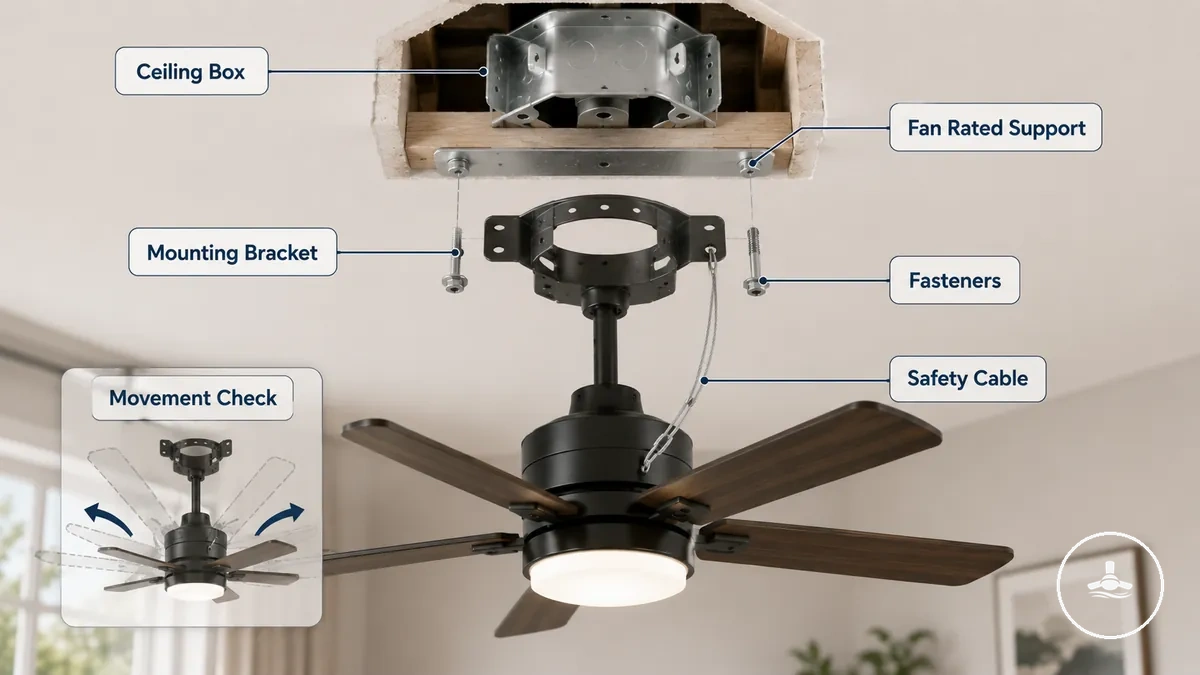
The support path is only as reliable as its weakest connection: structural attachment supports the rated box or brace, the bracket and specified fasteners connect the fan to that support, and the assembly must remain stable while the blades rotate. A secondary safety cable, where the manufacturer supplies or requires one, is additional retention rather than a substitute for a correctly rated primary mount.
Older ceiling boxes or replacement light fixture points can create uncertainty because they may not clearly indicate whether they are designed for fan-rated support. In such cases, the mounting condition may look acceptable but still lack the structural rating needed for a ceiling fan with light. This uncertainty typically requires verification against manufacturer instructions or qualified assessment when the support type cannot be confirmed visually.
Before reviewing detailed components, the safety checklist focuses on whether support and mounting conditions indicate stable, fan-rated installation readiness or potential risk requiring further inspection.
Support chain to verify
- Ceiling box → fan-rated label or documentation → confirms support confidence or requires verification
- Mounting brace → presence and fixed condition → reduces risk of structural movement
- Mounting bracket → tight attachment → ensures stable connection to ceiling support
- Fasteners → secure and intact → prevents loosening under operational movement
- Safety cable → properly attached → provides additional retention support in case of stress
Support box rating and ceiling brace condition
The support box and ceiling brace are acceptable only when their suitability for a ceiling fan and their structural attachment can be confirmed. An unknown box rating is an unknown safety condition: a visually tidy box does not establish that it is designed for the fan's load and movement.
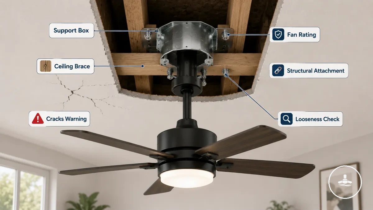
When a support box lacks clear fan rating documentation or the ceiling brace shows instability, the system may not provide reliable load distribution during fan operation. Visible cracks, looseness, or uncertain structural attachment can indicate reduced safety performance under weight and movement stress. In such cases, the condition must be treated as uncertain rating or compromised attachment, requiring professional verification before use. The checklist below confirms whether the support box rating and ceiling brace condition indicate safe structural attachment or require verification.
| Part | Observed state | Meaning / next action |
|---|---|---|
| Support box | Fan rating confirmed | Use only within the fan and support manufacturer's stated mounting conditions. |
| Support box | Rating unknown or not legible | Do not assume suitability; verify documentation or arrange qualified assessment. |
| Ceiling brace / structural attachment | Secure with no visible cracking or movement | Supports the visible case for stable mounting, but concealed structure is still not certified. |
| Ceiling brace / structural attachment | Cracking, looseness, sagging, or movement | Stop use and arrange qualified structural/mounting inspection. |
Mounting bracket, fasteners, and safety cable fit
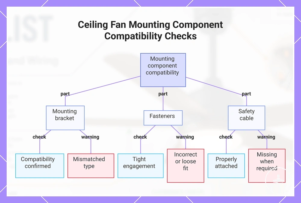
The mounting bracket and fasteners must match the fan's specified mounting system and engage the rated support securely. Hardware is not universally interchangeable, and a safety cable is relevant only where the fan design or installation instructions provide or require one; missing or substituted mounting hardware should be verified before use.
Mismatched brackets, loose fasteners, improvised substitutions, or a required retention cable that is not attached can reduce resistance to operating movement. Do not correct uncertain mounting by trial-and-error hardware substitution; confirm the specified parts or use a qualified installer.
Key checks focus on whether each mounting component matches the required fit and condition before operation.
- Mounting bracket → compatibility confirmed → ensures correct attachment alignment with fan system
- Fasteners (screws/bolts) → tight engagement → reduces loosening and movement under rotation
- Safety cable → properly attached (if provided) → supports secondary retention under load
- Mounting bracket → mismatched type → increases instability and requires stop-check
- Fasteners → incorrect or loose fit → increases vibration and movement risk
- Safety cable → missing when required → requires verification before safe use
This chart shows the three mounting components (bracket, fasteners, safety cable) and the key checks and warnings to ensure stable ceiling fan installation.
Weight support and movement resistance
Static support concerns the fan body, blades, and light kit at rest; movement resistance concerns how the complete mount remains secure during rotation, start-up, speed changes, and vibration. A support that carries the fan's weight without obvious sagging can still be unsuitable if its rating or attachment cannot resist fan operation.
Persistent or increasing wobble is therefore a movement signal, not proof that the ceiling support has failed. First distinguish blade-related imbalance from movement at the canopy or mounting point; movement of the ceiling attachment itself requires inspection rather than continued operation.
| Criterion | Value / condition to establish | Practical implication |
|---|---|---|
| Static support | Support rating and attachment are suitable for the complete fan/light assembly | Weight at rest is only one part of mounting safety. |
| Movement resistance | Bracket, fasteners, and structural attachment remain stable during operation | Operational stability must be assessed separately from static load. |
| Wobble pattern | Minor stable movement vs persistent, increasing, or mount-related movement | Increasing or mount-related movement is an inspection trigger. |
Blade clearance and low ceiling safety checks
Blade clearance depends on the fan's installed height, blade sweep, mounting type, room use, and any fixed or moving object that can enter the rotation zone. The useful value is not a guessed universal distance: the blade path must remain outside normal reach and obstruction paths and must meet the fan manufacturer's and applicable local clearance requirements.
Low ceilings and compact rooms reduce the margin for headroom, door swing, tall furniture, bunk beds, and raised platforms. Recheck clearance whenever the mounting configuration or room layout changes, because an object that is safe while stationary can enter the blade sweep during ordinary use.
If clearance is marginal or cannot be checked against the relevant instructions and local requirements, treat it as unverified rather than safe. A lower-profile fan can reduce overall drop in some rooms, while a downrod changes blade height in the opposite direction; the suitable configuration depends on the required operating space.
Clearance decision matrix
| Clearance area | What must stay clear | Risk signal | Decision rule |
|---|---|---|---|
| Floor / headroom | Normal occupied space below the rotating blades | People can readily reach or enter the blade zone | Verify installed height against manufacturer and local requirements before use. |
| Walls / doors | Full blade sweep, including a door's moving path | A door, wall edge, or fitting can enter the sweep | Reposition the obstruction or use a configuration that maintains clearance. |
| Furniture / bunk beds / platforms | Raised surfaces and objects beneath or beside the fan | Furniture or an elevated user position reduces separation from blades | Reassess the room layout before operation. |
| Mounting type | Blade height and ceiling spacing for the selected mount | Flush or downrod mounting creates a clearance conflict | Use only a manufacturer-supported mount that satisfies all clearances. |
Floor clearance and headroom risk
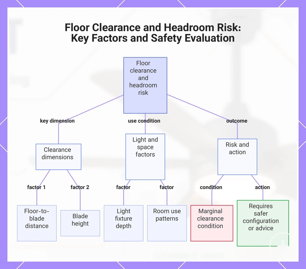
Floor clearance and headroom risk depend on the installed blade height, the depth of the light assembly, and how the space is used. A room with frequent traffic, raised-arm activity, elevated furniture, or children on bunks/platforms needs enough separation that the rotating blade path cannot be entered during ordinary use.
Do not use a subjective “feels high enough” test when headroom is close. Confirm the installed configuration against the fan instructions and applicable local requirements, and re-evaluate if furniture, flooring, or room use changes the effective distance to the blades.
Headroom conditions to recheck
- Floor clearance → reduced distance to blades → increased contact risk during movement
- Blade height → low mounting position → limited usable headroom in active spaces
- Light depth → extended fixture drop → reduced perceived overhead clearance
- Room use → high activity zones → higher likelihood of passing under blades
- Marginal clearance → tight vertical spacing → requires reassessment of setup safety
This chart outlines the main factors affecting floor clearance and headroom risk in ceiling fans with lights, including dimensions, room use, and required safety actions.
Wall, furniture, door, and bunk bed clearance
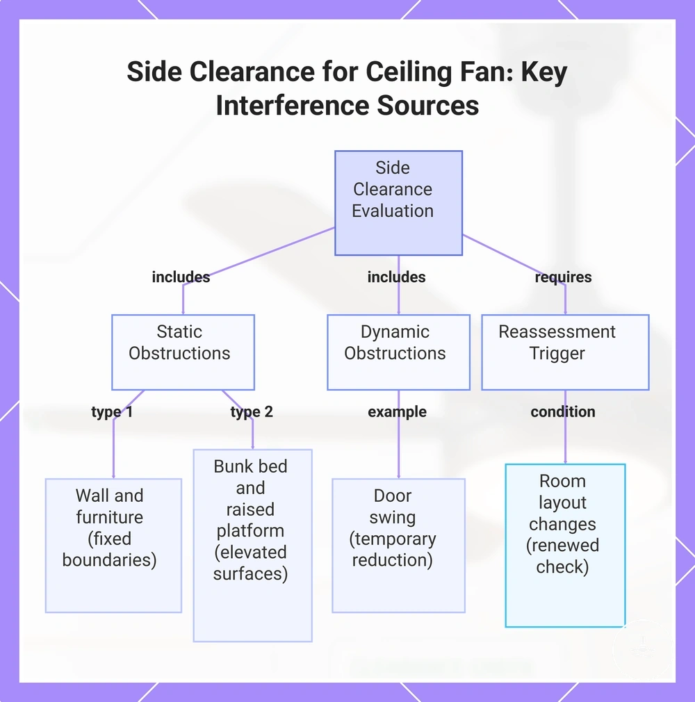
Side clearance is determined by the fan's full blade sweep and by anything that can move or place a person closer to that sweep. Walls are fixed boundaries, while doors, furniture, bunk beds, and raised platforms create different interference paths; each must remain outside the rotating blade zone during normal use.
In spaces with opening doors, tall furniture, or bunk beds, blade sweep interactions can change during normal room use. A door swing may temporarily reduce wall clearance, while furniture height or a raised platform can bring surfaces closer to blade movement. When room layout is adjusted or objects are moved, clearance conditions should be reassessed to maintain consistent safety assumptions. This is especially relevant in shared or frequently rearranged rooms.
| Interference source | How it changes clearance | Decision |
|---|---|---|
| Wall / fixed fitting | Creates a fixed boundary beside the blade sweep | Maintain the clearance required by the fan instructions and local requirements. |
| Door swing | Temporarily moves an obstruction into a different position | Open and close the door through its full path when checking the blade zone. |
| Tall furniture | Raises objects or users closer to the fan | Recheck after rearranging the room. |
| Bunk bed / raised platform | Raises a person's normal position toward blade height | Do not place an occupied elevated surface where a person can enter the blade path. |
| Room layout change | Can create a new obstruction after installation | Repeat the clearance check whenever tall or moving objects are relocated. |
This chart shows the main object-interference sources and conditions that affect side clearance for a ceiling fan with light.
Flush mount and downrod clearance conditions
Flush-mount and downrod configurations change the fan's vertical drop and blade height. A flush mount generally keeps the fan closer to the ceiling, while a downrod lowers the fan; neither is automatically safer because the correct choice must satisfy both ceiling spacing and occupied-space clearance for that model.
Use only mounting configurations supported by the fan manufacturer. On sloped or vaulted ceilings, the mounting system must also support the ceiling angle and maintain the required blade clearance throughout the sweep; see sloped ceiling mounting when angle and drop are part of the installation decision.
| Mounting condition | Effect on blade position | Main clearance trade-off | Verify when |
|---|---|---|---|
| Flush / low-profile mount | Keeps the fan closer to the ceiling | Can improve headroom but may require model-specific ceiling spacing | Ceiling height is limited or the fan has a dedicated low-profile configuration. |
| Downrod mount | Lowers the fan by the selected, supported drop | Can improve placement relative to the ceiling but reduces headroom | The room is tall enough and the downrod length is approved for the model. |
| Sloped / vaulted ceiling | Changes suspension geometry and may require a compatible adapter | Blade sweep must remain clear at the ceiling angle | The fan, bracket/adapter, downrod, and ceiling angle must be compatible. |
Wiring and light electrical safety checks
Wiring and light checks should identify visible electrical warning signs without turning the checklist into electrical work. Before close inspection, isolate the circuit where this can be done safely; do not touch exposed conductors, open fixed-wiring connections, or attempt electrical testing as part of this checklist. Electrical testing and work on fixed wiring should be handled by a licensed electrician under applicable local requirements.
The fan motor and light may be controlled by separate switched conductors, by a shared supply through a receiver/controller, or by another manufacturer-specific arrangement. The relevant EAV is therefore control path → model/installation specific → verify against the wiring diagram, not an assumption that every fan-light uses the same circuit layout. Earthing and connector condition must likewise match the product and installation requirements.
Persistent flickering, abnormal buzzing, scorching, a burning smell, exposed conductors, or repeated breaker trips are escalation signals. Sparks, burning odour, visible heat damage, exposed live parts, or repeated protective-device operation are stop-use conditions; persistent flicker or buzzing also warrants investigation rather than repeated resetting or continued operation.
| Electrical area | Safe visible condition | Warning signal | Response |
|---|---|---|---|
| Power / isolation | Circuit is isolated before any close non-contact inspection | Isolation is uncertain or live parts may be exposed | Stop; do not proceed into electrical testing or contact. |
| Controls | Fan and light respond consistently with the intended control arrangement | Irregular operation, persistent flicker, or unexplained control behaviour | Use the model wiring information; arrange licensed inspection if the cause is electrical or unclear. |
| Connectors / earthing | Connections remain enclosed with no visible exposed copper, scorching, or damage | Exposed conductor, loose/damaged enclosure, or uncertain earthing | Do not operate until inspected. |
| Light kit | Secure cover and no burning smell, visible heat damage, or exposed socket/contact | Burning smell, heat damage, exposed electrical part, or repeated fault | Stop use and arrange qualified inspection. |
Breaker isolation and live wire risk
Breaker isolation is a safety boundary before close inspection, not proof that a conductor is de-energised. Switch the relevant circuit off at the switchboard when this can be done safely, keep the inspection non-contact, and do not proceed if isolation cannot be established without electrical testing.
Caution: An ordinary wall switch is not a substitute for safe electrical isolation when wiring could be exposed.
- Identify and switch off the relevant circuit at the switchboard before a close visual inspection.
- Keep covers in place and do not touch conductors or terminals.
- Stop if the circuit, isolation point, or power state is uncertain.
- Use a licensed electrician when testing, fixed-wiring access, or fault-finding is required.
If the power state is uncertain, the checklist cannot safely resolve that uncertainty. Treat it as an inspection boundary and arrange licensed electrical verification rather than attempting contact-based checks.
Fan, light, switch, and remote wiring separation
Fan and light functions can be controlled in several ways: separate wall-switched conductors, a shared supply feeding a remote receiver/controller, or a model-specific electronic control system. Independent behaviour does not by itself prove a wiring fault; it must be interpreted against the fan's intended control design.
If the fan and light respond differently from the documented control scheme, or if conductors are unidentified, do not infer the wiring arrangement from behaviour alone. Use the manufacturer wiring diagram and have fixed-wiring uncertainty checked by a licensed electrician.
| Control element | Possible role | What the checklist can conclude |
|---|---|---|
| Fan motor | Motor/load controlled by wall wiring, receiver, or integrated electronics | Its behaviour must match the documented control design. |
| Light circuit / LED driver | Separate or shared control path depending on model | Independent light behaviour can be normal in some designs. |
| Wall control | May switch supply, provide separate fan/light control, or communicate with electronics | Do not assume conductor count or function without the wiring diagram. |
| Remote receiver / controller | May distribute one supply to fan and light functions | A shared supply can still provide separate functional control. |
| Unidentified conductors | Unknown fixed-wiring function | Licensed electrical verification is required rather than trial connection. |
Wire connectors, earthing, and covered connections
Wire connectors and enclosures must keep conductors securely terminated and inaccessible, while protective earthing must match the fan and installation requirements. A visual check can identify exposed copper, scorching, damaged insulation, or a displaced cover, but it cannot establish connector torque, conductor sizing, or earth continuity.
Loose-looking connectors, exposed copper, scorching, damaged insulation, or a canopy that pinches or strains conductors are reasons to stop use and arrange electrical inspection. Do not push, retighten, or rearrange fixed wiring as a visual-check step.
- Exposed copper or damaged insulation: do not operate; arrange electrical inspection.
- Scorching, melted material, or burning odour: stop use and isolate the circuit if this can be done safely.
- Loose/displaced canopy or cover: do not assume the internal connections remain protected.
- Earthing uncertain: treat continuity as unverified; visual appearance is not a test.
- Crowded or pinched conductors: do not manipulate them; have the wiring arrangement checked.
Light kit heat, clearance, and exposed component risks
The light kit adds thermal and electrical conditions to the fan assembly. Replaceable lamps must match the lamp type and maximum rating specified by the manufacturer; integrated LED modules should be treated according to the model instructions rather than as ordinary replaceable bulbs. Shades, diffusers, and covers must remain secure and intact so internal components are not exposed.
Persistent flicker or buzzing can indicate a lamp, driver, control, or connection issue, while burning smell, visible scorching, melted material, or exposed electrical contacts are stronger warning signs. Stop use immediately for burning, scorching, exposed contacts, or obvious heat damage; investigate persistent flicker or buzzing before treating it as normal.
| Light-kit element | Required condition | Warning / decision |
|---|---|---|
| Replaceable lamp | Type and wattage/ratings match the fan-light instructions | Do not substitute a higher or incompatible lamp rating. |
| Integrated LED / driver | Operates without persistent flicker, abnormal buzzing, smell, or visible heat damage | Fault symptoms require model-specific service or qualified inspection. |
| Shade / diffuser / cover | Secure, intact, and correctly fitted | Loose, cracked, or missing protection should be corrected before use. |
| Socket / electrical contact | Not exposed to touch in normal assembled condition | Exposed contact or conductor is a stop-use condition. |
| Heat damage | No scorching, melting, or burning odour | Stop use and arrange inspection; do not keep cycling the light to test it. |
Wobble, vibration, and loose part checks
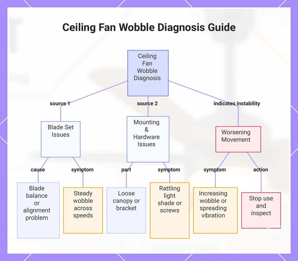
Wobble should be classified by severity, persistence, source, and whether it increases with speed. Small stable movement can differ from severe or worsening wobble, but movement at the canopy or ceiling attachment is more concerning than a blade-only imbalance because it can point to mounting looseness.
Blade imbalance, blade-arm alignment, a loose shade, or loose screws can each create different vibration patterns. Observe from a safe position rather than touching a running fan: blade-related wobble tends to track the rotating assembly, while canopy or bracket movement is concentrated near the ceiling mount. The pattern narrows the next check but does not prove a single cause.
A newly installed fan should not be assumed to need a “settling” period. Unexpected wobble after installation can reflect blade assembly, balance, bracket, fastener, or support issues, while older fans can develop looseness or blade changes over time. Severe, increasing, or mount-related movement is a stop-use and inspection condition.
Wobble diagnostic matrix
| Observed source / signal | Possible interpretation | Safe next step |
|---|---|---|
| Blade set moves unevenly while mount remains stable | Blade damage, blade-arm alignment, or balance issue | Stop the fan before any blade check; follow the manufacturer's balance/alignment procedure if appropriate. |
| Canopy or bracket moves at the ceiling | Possible mounting or structural looseness | Stop use and arrange mounting/support inspection. |
| Shade or visible fastener rattles/shifts | Loose light-kit or hardware component | Stop the fan; do not continue operating with a visibly loose part. |
| Wobble becomes stronger or spreads with speed | Increasing dynamic instability | Stop use rather than testing repeatedly at higher speed. |
This chart shows how to assess wobble and vibration in a ceiling fan by identifying the source, movement pattern, and required safety action.
Blade balance and alignment problems
Blade imbalance or blade-arm misalignment can cause wobble, but similar movement can come from loose mounting or structural problems. A blade diagnosis is therefore provisional: do not keep balancing a fan if the canopy, bracket, or ceiling attachment is moving.
Warped, damaged, mismatched, or misaligned blades can disturb rotation. With the fan stopped and safely isolated for any close inspection, compare blade condition and attachment against the manufacturer's instructions; a balancing kit can address some imbalance patterns, but failure to improve or any mount movement calls for deeper inspection.
Blade-focused checks
- Blade damage → warped blade or physical defect → uneven rotation pattern
- Blade alignment → blade arm misalignment or uneven blade set → movement imbalance
- Balancing kit attempt → correction applied → limited or no improvement
- Persistent wobble → wobble continues after adjustments → inspection required signal
Loose canopy, shade, screw, and bracket signs
Visible looseness in the canopy, shade, screws, or bracket changes the condition from ordinary operating vibration to a specific hardware warning. Rattle alone is not a diagnosis, but a visible gap, shifting part, missing fastener, or movement at the ceiling attachment is a reason to stop operation until the cause is resolved.
Repeated rattle that changes with speed can come from a loose shade or other hardware, while movement of the canopy or bracket points closer to the mounting system. Do not tighten parts while the fan is running; if access would involve fixed wiring or uncertain support, use a qualified professional.
Visible part → warning state → response
| Part | Warning state | Response |
|---|---|---|
| Canopy | Gap, shifting, or movement relative to the ceiling | Stop use; inspect mounting/support rather than treating it as cosmetic. |
| Shade / diffuser | Rattle, looseness, crack, or unstable fit | Stop use until the light cover is secure and intact. |
| Fasteners | Missing or backing out | Stop use; verify the specified hardware and mounting condition. |
| Bracket / ceiling attachment | Shifting, visible movement, or structural noise | Stop use and arrange qualified mounting/support inspection. |
Unsafe signs that need professional inspection
Some observations should move the fan immediately out of routine checklist mode. Electrical arcing/sparks, burning smell, repeated breaker trips, exposed conductors, severe or increasing wobble, a sagging mount, visible cracking, or movement at the ceiling attachment are stop-use signals; they require the relevant electrical, mounting, or structural condition to be checked before normal operation resumes.
For electrical warning signs, isolate the circuit if this can be done safely and use a licensed electrician. For sagging, cracking, or uncertain ceiling support, use an appropriately qualified installer or building professional as needed. Do not use the related installation limits as permission to keep operating through an active warning sign.
Persistent flickering or buzzing is less specific than sparks or a burning smell, but it still deserves investigation, especially if it appears with heat, odour, breaker operation, or irregular fan/light control. The flickering light warning signs guide can help separate lamp/control symptoms from stronger electrical escalation signals.
Stop-use and inspection triage
| Signal category | Examples | Response |
|---|---|---|
| Electrical | Sparks/arcing, burning smell, repeated breaker trips, exposed conductor, scorching | Stop use; isolate if safe; arrange licensed electrical inspection. |
| Structural / mounting | Sagging mount, cracking, canopy/bracket movement, uncertain support attachment | Stop use; arrange qualified mounting/structural inspection. |
| Movement | Severe or increasing wobble, especially with mount movement | Stop use; do not keep increasing speed to reproduce the symptom. |
| Light / control | Persistent flicker or buzzing without stronger warning signs | Investigate before treating as normal; escalate promptly if heat, smell, exposed parts, or breaker operation appears. |
This chart categorizes the main warning signs for ceiling fans with lights into electrical, structural, and movement indicators, along with the required response.